Comtech EF Data CRS-311 User Manual
Page 32
CRS-311 1:1 Redundancy Switch
Revision 7
Introduction
MN/CRS311.IOM
1–8
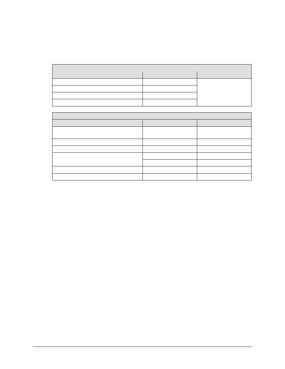
1.3.4 CDM-Qx/QxL, SLM-5650/5650A Modem Interface Modules
The following tables indicate which TMI (Traffic Modem Interface) and RMI (Redundant Modem
Interface) should be used with each modem and data interface type:
CDM-Qx/QxL Modem
Data Type
TMI Type
RMI Type
EIA-530/422/V.35, EIA-232
CRS-316
CRS-305
G.703 T1/E1 Bal D&I , Unbal
CRS-325
HSSI CRS-336
Quad E1
CRS-365
SLM-5650/5650A Modem
Data Type
TMI Type
RMI Type
EIA-530/422 or GbE (Single-port Ethernet Bridge
Mode)
CRS-316
Note 1
CRS-307
Note 1
G.703 Bal/UnBal
CRS-325
CRS-306
HSSI or GbE (Single-port Ethernet Bridge Mode)
CRS-336
Note 1
CRS-306/307
Note 1
Vipersat (or Single-port Ethernet Router Mode)
CRS-316
Note 1
CRS-307
Note 1
CRS-515 CRS-505
3-Port Ethernet (Ethernet Bridge Mode)
CRS-515 (Ports 2,3,4)
CRS-505 (Ports 2,3,4)
4-Port Ethernet
See Note 2
(Ethernet Router Mode)
CRS-515 (all 4 ports)
Note 2
CRS-515 (all 4 ports)
Note 2
Important Notes:
1. Gigabit Ethernet (referred to as either GbE or GigE), when associated with the CRS‐316/336
TMI modules can mean either:
(a) The Gigabit Ethernet interface provided by the optional single‐port 10/100/1000
Base‐T (GbE) Interface Module, or
(b) A single port (“Port 1”) of the 4‐port Network Processor (NP) Interface Module,
configured for Ethernet Bridge Mode (not Ethernet Router Mode) operation. The 4‐
port Ethernet data type is always associated with the Network Processor module in
the SLM‐5650/5650A, and can be configured in either Ethernet Bridge Mode or
Ethernet Router Mode.
1:1 Redundancy is supported for Vipersat remote terminals, without the need for hardware
upgrades to the CRS‐505 RMI and CRS‐515 TMI modules, by using the CRS‐307 RMI and
CRS‐316 TMI modules.
For the CRS‐307 RMI and CRS‐316 TMI modules to work, it is required to connect the
primary and backup Network Processor Modules via Ethernet. This can be accomplished by
connecting the primary and backup NPs via a crossover Ethernet cable, or via a separate
external Ethernet Switch.