100 amp, H35 & n, Operation – Hypertherm HD3070 Plasma Arc Cutting System w/ Automatic Gas Console User Manual
Page 124: Plasma / n, Shield 100 amp cutting
HD3070 with Automatic Gas Console
Instruction Manual
4-35
16
OPERATION
Material
Thickness
(in)
(mm)
Arc
Voltage
(volts)
Torch
Standoff**
(in)
(mm)
Travel
Speed
(ipm)
(m/min)
Pierce
Delay
(dial)
(sec)
Initial
Piercing
Height
(in)
(mm)
1/4
6.4
45
45
60
60
30
30
134
0.120
3.0
75
1.9
0.200
5.1
0
0.1
3/8
9.5
45
45
60
60
30
30
144
0.150
3.8
65
1.6
0.200
5.1
0.5
0.2
1/2
12.7
45
45
60
60
50
40
160
0.250
6.4
45
1.1
0.300
7.6
1
0.3
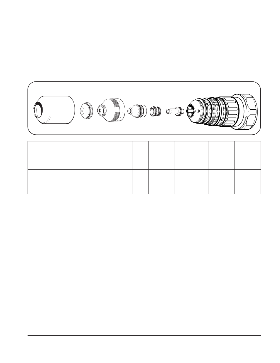
Shield
120594
Nozzle
120591
Electrode
120589
Retaining Cap
120592
Swirl Ring
020590
PAC186 Torch
120349
Shield Cap
020634/020687
PAC186
Stainless Steel
H35 & N
2
Plasma / N
2
Shield
100 Amp Cutting
H35 and N
2
gas inlet pressures must be between 105 - 135 psi (7.2 - 9.2 bar) for all material thickness.
#
Refer to LCD display Figure 4-3.
** Torch standoff tolerances are ± 0.005 inch (± 0.125 mm). When using a THC, tolerances are ± 1 volt.
If the part is not completely cut away from the scrap, try modifying the leadout. Stop the cut 0.050 inch (1.3 mm) before the end
of the part for 1/4 and 3/8 inch (6.4 and 9.5 mm) material and 0.100 inch (2.5 mm) for 1/2 inch (12.7 mm) material. The ramp
down of the current and gases will complete the cut. If your program can not be modified, reduce cutting speed and use no
leadout.
Counter clockwise (CCW) consumables are available for mirror image cutting. Refer to Section 6, Parts List.
If problems occur with the cutting process, and the flowrates are suspect, refer to Section 5, Maintenance, Gas System Back
Pressure Checks.
Test Cut
Flowrates (%)
Shield
N
2
N
2
(3)
#
(4)
#
Plasma
N
2
H35
(5)
#
(6)
#
Test Preflow*
Flowrates (%)
Preflow
N
2
N
2
(1)
#
(2)
#