Maintenance – Hypertherm HD3070 Plasma Arc Cutting System w/ Automatic Gas Console User Manual
Page 197
5-72
HD3070 with Automatic Gas Console
Instruction Manual
16
MAINTENANCE
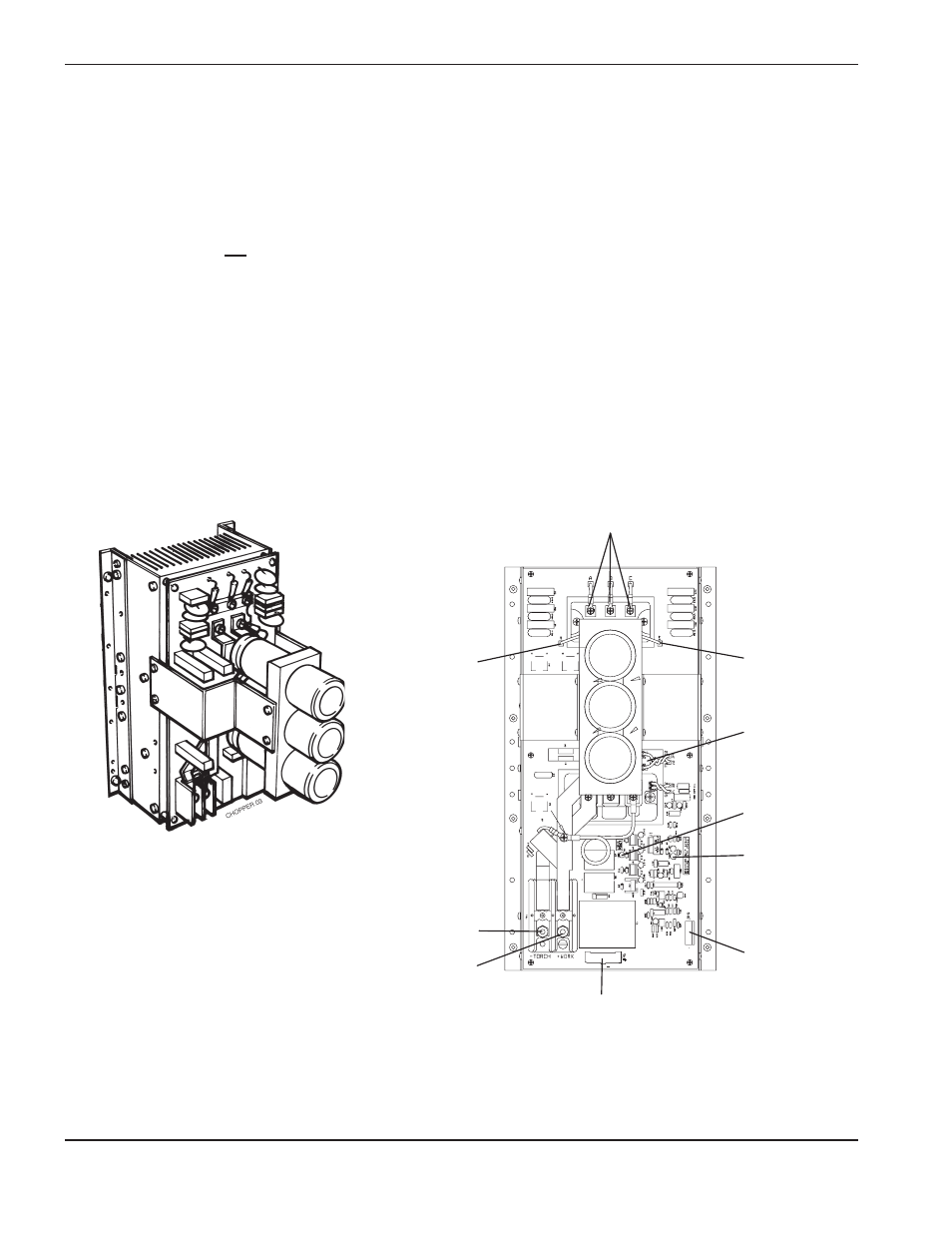
Figure 5-9
CH130 Chopper Module – Front View
LED1
JP9
LED3
Thermo
Switch
TS1
Bridge (–)
Bridge (+)
JP6
(+) WORK
(-) TORCH
C H O P P E R . 0 1
Input
5. If voltage from step 4 is +280 VDC and corresponding fuse is not blown, check the chopper output at TB1 by
placing the positive lead of the voltmeter at the (+) WORK terminal (#48A output cable) and the negative lead at
the (-) TORCH terminal (#39A output cable). See Figure 5-9.
6. Turn the system on and press the START command. After the START command has been given, check the
voltage. If the output from the chopper at these points is +280 VDC, the chopper is OK.
7. If the chopper does not output +280 VDC, check to see if LED1 logic power light is on. If LED1 is not on, check
if 120V is going to JP6. If there is no 120V at JP6, check wiring back to power distribution board. Repair or
replace defective component(s), if necessary.
Also check to see if LED3 is turning green when enabled (normal condition). If LED1 is on and LED3 is red
when enabled (fault condition), then make sure that JP9 is seated properly. If JP9 is connected, disconnect one
side of the thermo switch wire (TS1) and try again. If voltage comes up and LED3 turns green, the unit is either
too hot or thermo switch is shorted. Allow unit to cool and repeat test. If LED3 still turns green, replace chopper
module.