Gas console -67, Maintenance, Gas console – Hypertherm HD3070 Plasma Arc Cutting System w/ Automatic Gas Console User Manual
Page 192
HD3070 with Automatic Gas Console
Instruction Manual
5-67
16
MAINTENANCE
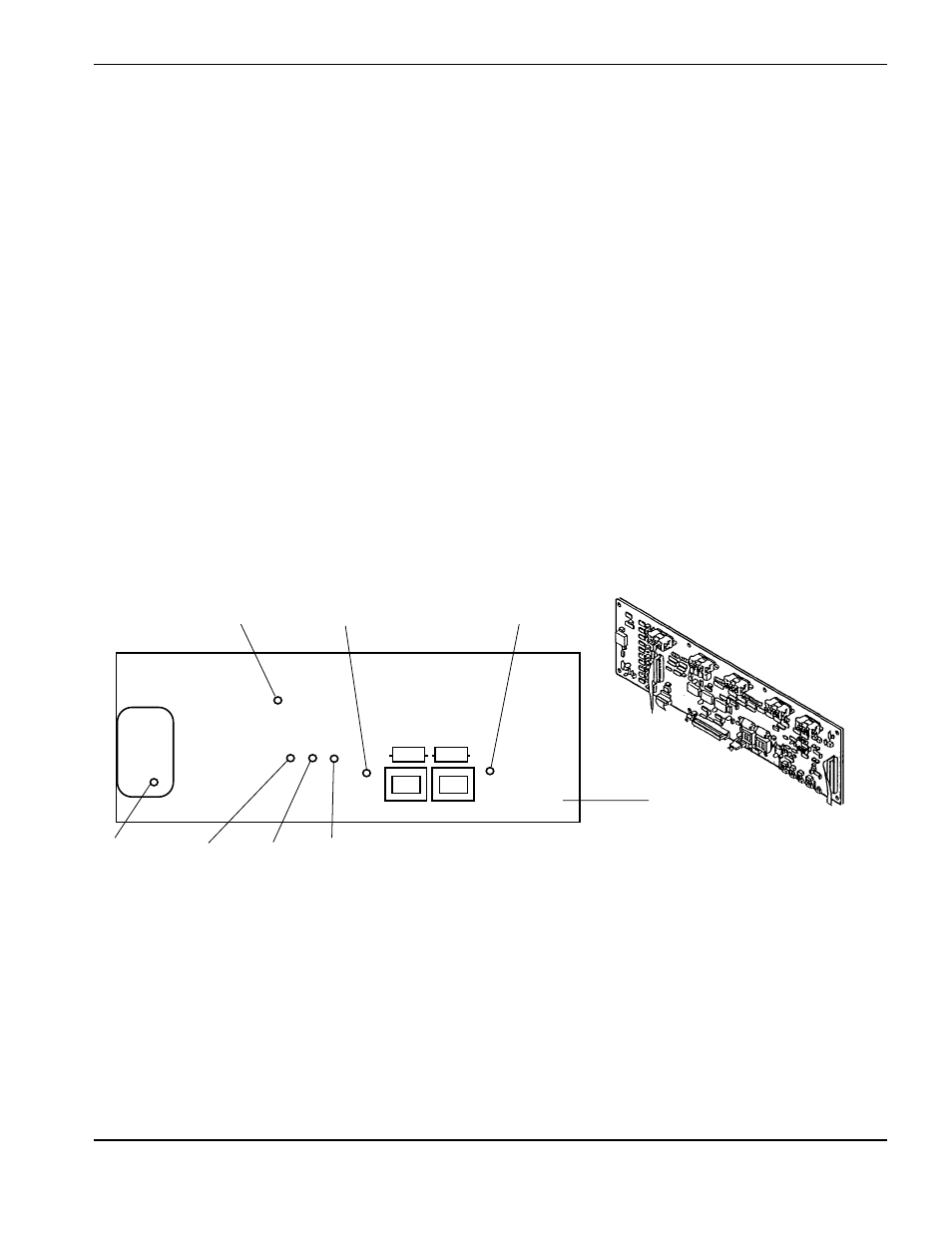
Figure 5-8
Gas Console Control Board LED Locations
Gas Console
The control board A1 provides LEDs to notify the user when certain voltages are present and when other certain
functions occur in the HD3070 system as described below. The gas console cover and front panel must be
removed to observe the LEDs (Figure 5-8).
• LED1 – Flashes to indicate an error. Refer to Error Codes and Messages, Gas Console Error Codes earlier
in this section.
• LED2 – Spare (not used.)
• LED3 –Illuminates to indicate that input gas supplies are within correct range of 0.73 – 0.93 MPa, 7.2 – 9.3
bar, 105-135 psig.
• LED4 – Illuminates to indicate that the gas system has no operational errors.
• LED5 – Illuminates to indicate that +12 volts is applied to PCB
• LED6 – Illuminates to indicate that -12 volts is applied to PCB.
• LED7 – Illuminates to indicate that +5 volts is available to microprocessor.
LED4
LED6
LED5
LED7
LED1
LED2
LED3
Control Board A1