Hypertherm HD3070 Plasma Arc Cutting System w/ Automatic Gas Console User Manual
Page 134
HD3070 with Automatic Gas Console
Instruction Manual
5-9
16
MAINTENANCE
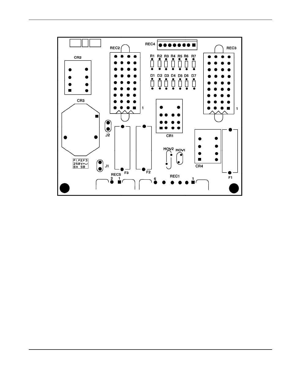
6. Measure voltage at Power Distribution Board 1XPCB2. Refer to Figure 5-2 for detail of 1XPCB2. Also refer to
applicable wiring diagram at back of manual, if required. Look on the board for fuses F1, F2, and F3.
Measurements between each fuse and chassis ground should be as follows:
F1:
24VAC
F2:
120VAC
F3:
240VAC
If voltages are not present, or incorrect at one or more of these points, disconnect power and troubleshoot
1XPCB2 fuses and associated pins, connectors and wiring between power distribution board connector REC1
and transformer secondary T1. Refer to Figure 6-7 for location of T1.
Check main power fuses F1, F2, and F3 located in Figure 6-3, and associated wiring and connections between
T1 and L1 and L2 (including linkboard on 240/480V units).
Repair and/or replace defective component(s) if necessary.
Figure 5-2
Power Distribution Board 1XPCB2
ASSY NO REV SERIAL NO
POWER DISTRIBUTION