Nstallation – Yaesu FTM-10R User Manual
Page 18
16
FTM-10R O
PERATING
M
ANUAL
S
EPARATE
I
NSTALLATION
I
NSTALLATION
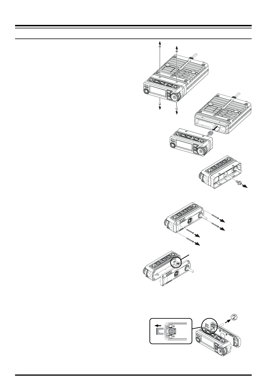
1. Remove the four screws securing the
Front Panel and then remove the Front
Panel from the Transceiver Body
(Figure 1).
2. Disconnect the 8-pin modular plug
from the Transceiver (Figure 2).
3. Remove the screw affixing the Straight
Sub Panel, and then remove the
Straight Sub Panel from the Front Panel
(Figure 3).
4. Remove the four screws securing the
Rear Case of the Front Panel and re-
move the Rear Case from the Front
Panel (Figure 4). Disconnect the Con-
nector of the Connection Cable from
the Printed Circuit Board in the Front
Panel when you remove the Rear Case
(Figure 5).
5. Remove the Binding Plate from the
Rear Case (Figure 6-), and then pull
out the Connection Cable from the Rear
Case (Figure 6-).
Figure 1
Figure 2
Figure 3
Figure 4
Figure 5
connector
Figure 6