Nstallation – Yaesu FTM-10R User Manual
Page 23
21
FTM-10R O
PERATING
M
ANUAL
N
ON
-S
EPARATE
I
NSTALLATION
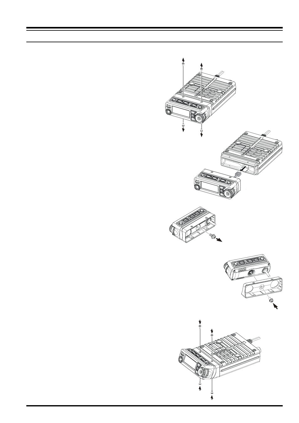
The FTM-10R front panel may be tilted using the supplied Angle Sub Panel.
Figure 1
Figure 2
Figure 3
Figure 4
Figure 5
1. Remove the four screws securing the
Front Panel and then remove the panel
from the transceiver body (Figure 1).
2. Disconnect the 8-pin modular plug
from the transceiver (Figure 2).
3. Remove the screw affixing the Straight
Sub Panel, and then remove the
Straight Sub Panel from the Front Panel
(Figure 3).
4. Attach the supplied Angle Sub Panel
to the Front Panel, using the previously
removed screw.
You may set this up in a “look-up” or
“look-down” configuration depending
on the mounting position of the Sub
Panel.
5. Connect the 8-pin modular plug to the
transceiver’s body.
6. Attach the Front Panel (with Angle Sub
Panel) to the transceiver’s body, using
the previously removed four screws
(Figure 5).
I
NSTALLATION