Nstallation – Yaesu FTM-10R User Manual
Page 19
Advertising
17
FTM-10R O
PERATING
M
ANUAL
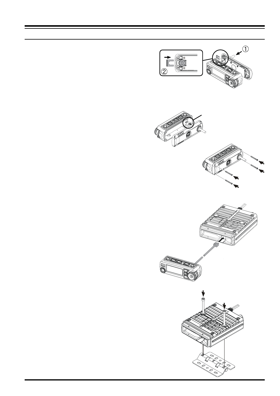
6. Insert the supplied 3-m Connection
Cable from the rear side of Rear Case
(Figure 7-), and then attach the Con-
nection Cable to the Rear Case using
the previously removed Binding Plate
(Figure 7-).
6. Attach the Connection Cable to the
Printed Circuit Board (Figure 8), and
then replace the Rear Case to the Front
Panel using the previously removed
four screws (Figure 9).
7. Connect the 8-pin modular plug of the
Connection Cable to the Transceiver
(Figure 10).
9. Mount the supplied Mobile Mounting
Bracket to the any position using the
supplied screws (Figure 11).
I
NSTALLATION
Figure 7
Figure 8
Figure 9
Figure 10
Figure 11
S
EPARATE
I
NSTALLATION
connector
Advertising