Chapter 4. cabling diagram for the scon, Cabling diagram for the scon, Cabling diagram for – Visara SCON-20L Installation User Manual
Page 55: Chapter 4. cabling diagram for the scon -1
707054-005
4-1
Chapter 4. Cabling Diagram for
the SCON
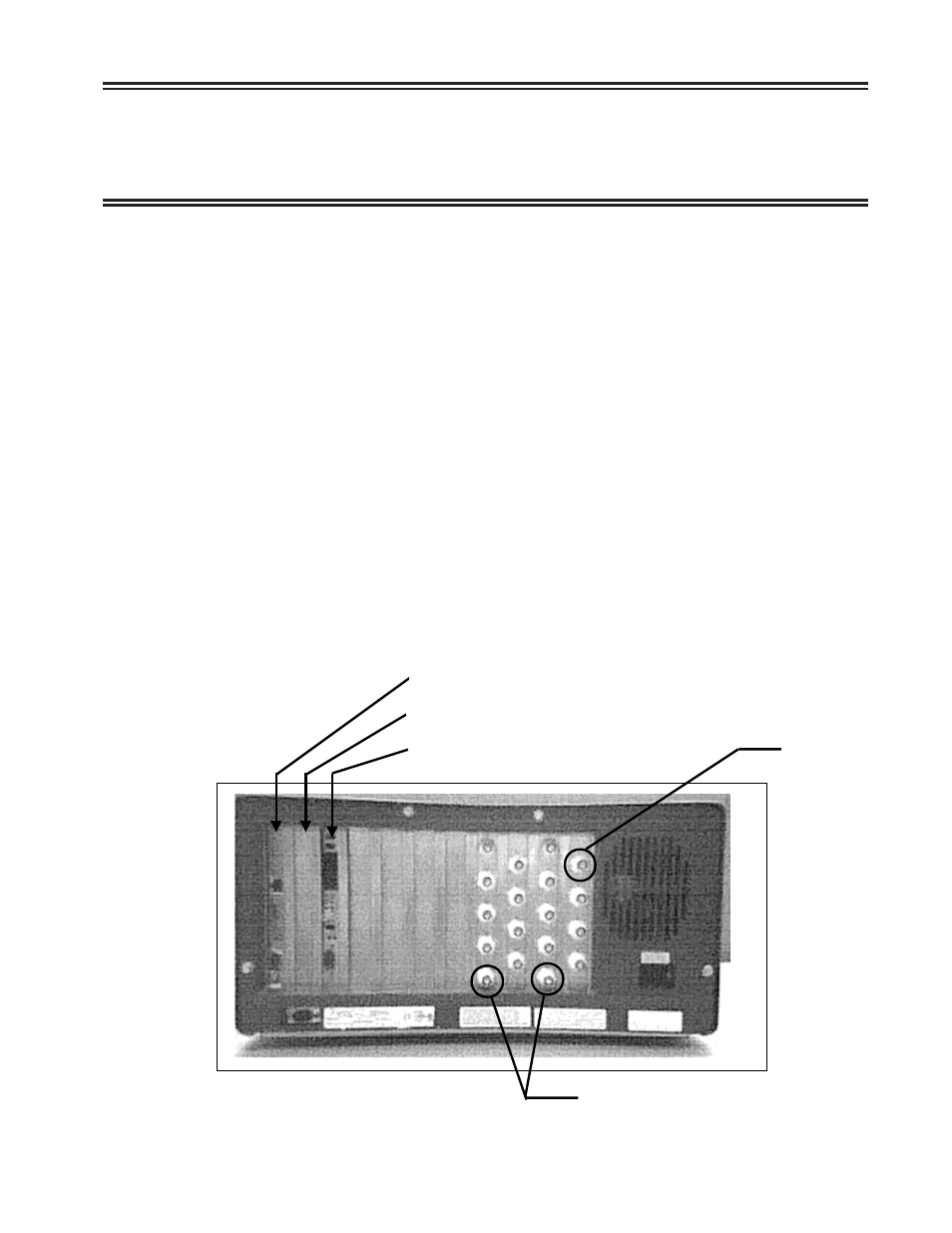
The diagram below shows the rear of the SCON-20L or SCON-22L, where all of the
cables are connected. A second 18-port Coax Device Adapter (CDA) can be mounted
between the CDA shown and the ESCON card shown (SCON-22L only). When two
CDAs are installed, the card on right, as viewed from the rear of the unit, is considered
to be CDA1 and the other card would be CDA2. Note that the port numbering on each
card will start at 0, but on CDA2 0 actually represents port 16. Refer to the
SCON-20L/22L Hardware Reference manual for further information.
Coax Device Cabling Options:
• Direct attach all coax devices to one or two CDAs
• Use 8-port multiplexers to attach some or all of the 32 devices (16 on 20L)
• Use 16-port multiplexers to attach some or all of the 32 devices (16 on 20L)
• Use one 32-port multiplexer to attach all 32 devices (16 on 20L)
• Use a combination of direct-attached, 8-port, and 16-port multiplexers
The references to first and second interface cards apply when there are 2 FET cards
installed, to distinguish which one the software is referring to. If only one interface
card is installed, then it will naturally be the first.
ESCON Interface
Second Network Interface (SCON-22L only)
First Network Interface
Coax
Port 0
Mux-only coax ports