3 connecting servomotor to machine, 4 protective structure – Yaskawa Sigma-5 Series User Manual:: For Use with Large-Capacity Models-Setup. Rotary Motors User Manual
Page 28
2 Installation
2.2.3 Connecting Servomotor to Machine
2-6
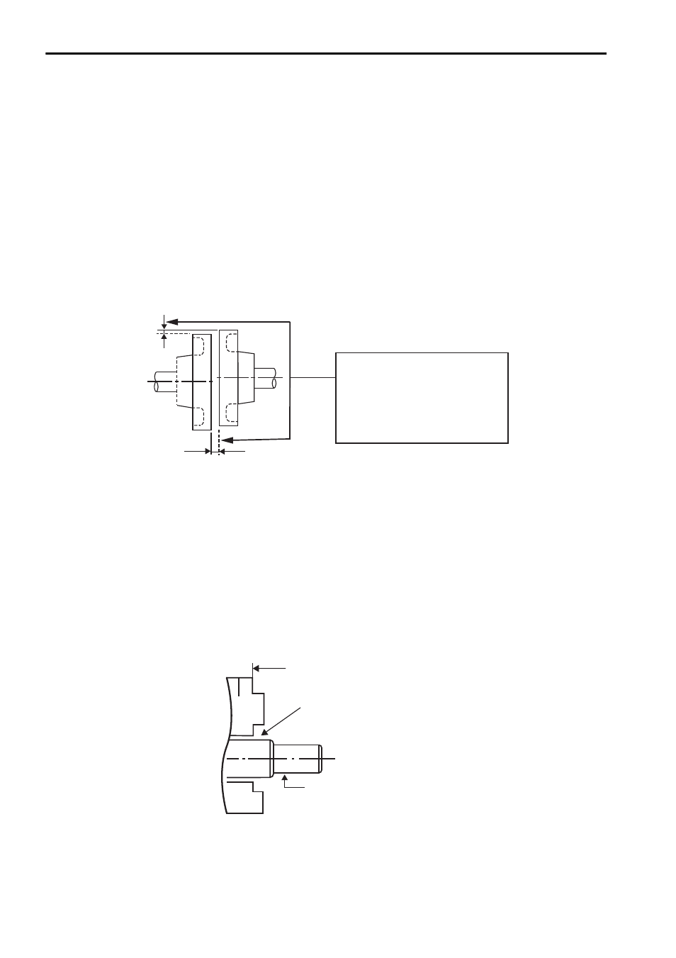
2.2.3 Connecting Servomotor to Machine
The end of the motor shaft is coated with anticorrosive paint. Thoroughly remove the
paint before installation.
Align the shaft of the servomotor with the shaft of the machine, and then couple the
shafts. Install the servomotor so that alignment accuracy falls within the following
range. Vibration will damage the bearings or encoders if the shafts are not properly
aligned.
Do not allow direct impact to be applied to the shafts when installing the coupling as
the encoder mounted on the opposite end of the shaft may be damaged.
2.2.4 Protective Structure
The servomotor’s protective structure
*
is totally enclosed and cooled separately with
an IP44.
∗ Except through shaft section. The protective structure specifications can be satisfied only
when using a specified cable.
When the through shaft section is subject to oil exposure, refer to 2.2.5 Other Pre-
cautions.
Measure this distance at four
different positions on the
circumference. The difference
between the maximum and
minimum measurements must be
0.03 mm or less.
(Turn together with coupling.)
Alignment Accuracy
Through shaft section
Shaft
Flange
This refers to the gap where
the shaft protrudes from
the end of the motor.