Yaskawa Sigma-5 Series User Manual:: For Use with Large-Capacity Models-Setup. Rotary Motors User Manual
Page 91
3.6 Selecting and Connecting a Dynamic Brake Unit
3-43
Wiring and Connection
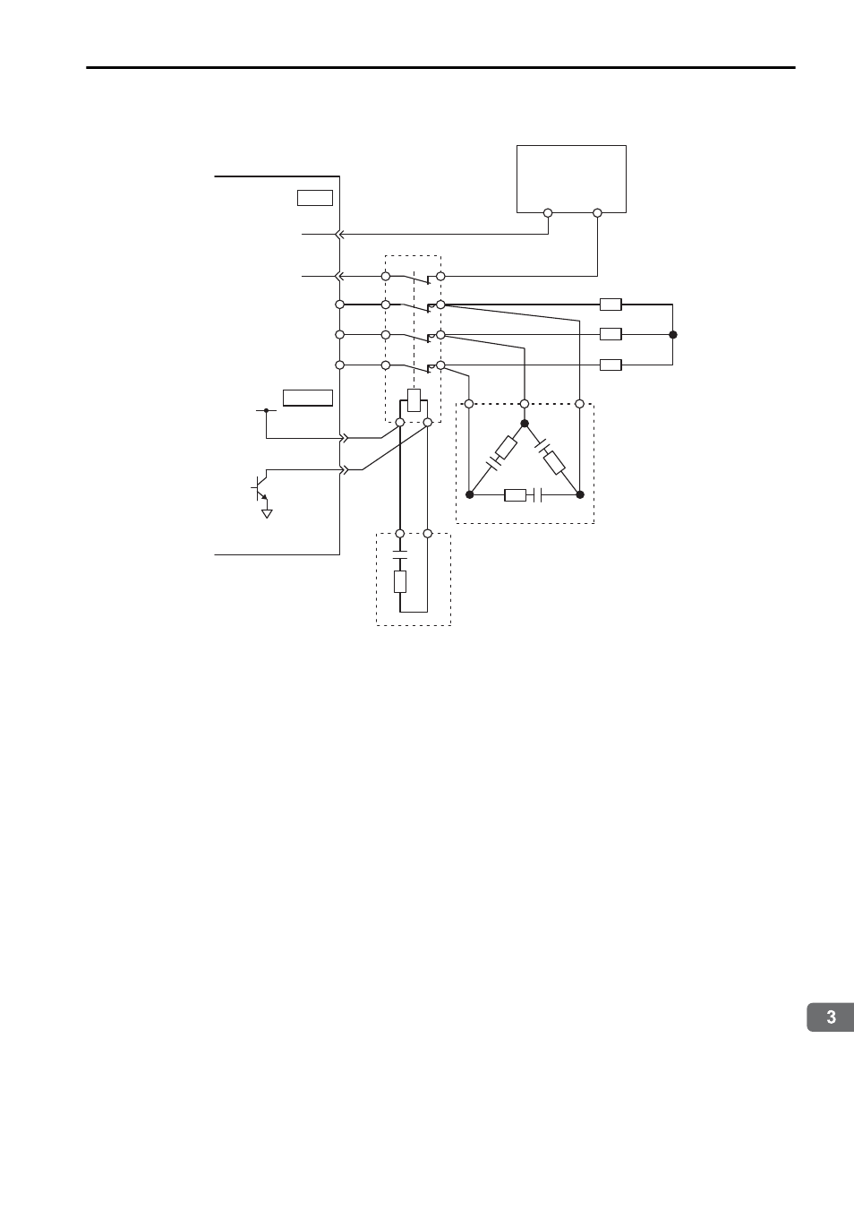
• Using NC Contacts for the Dynamic Brake Contactor
∗ The above figure is for using a dynamic brake contactor with NC contacts. The dynamic
brake answer signal (a signal from NC auxiliary contacts) is input to CN1-45. To indicate an
error if the input signal to CN1-45 turns OFF (open) while the dynamic brake is activated, the
Pn515 parameter in the SERVOPACK must be set to n.E. If the dynamic brake answer
signal is not used, Pn515 is set to n.8 (default setting).
Note: 1. If you assign more than one signal to the same input circuit, OR logic will be used
and any of the input signals will cause the circuit to operate. This may result in unex-
pected operation.
2. The maximum current for DB24 and DBON is 300 mA.
DV
DU
DW
SERVOPACK
24 V
For I/O
power supply
0 V
(Auxiliary contacts)
Dynamic brake resistor
DBON
DB24
Dynamic brake contactor
Main circuit surge
absorption unit
Coil surge
absorption unit
CN115
24 V
DB
47
45*
CN1
0 V
DB