4 main circuit wiring, 1 names and functions of main circuit terminals, Servopack – Yaskawa Sigma-5 Series User Manual:: For Use with Large-Capacity Models-Setup. Rotary Motors User Manual
Page 63
3.4 Main Circuit Wiring
3-15
Wiring and Connection
3.4
Main Circuit Wiring
The names, specifications, and functions of the main circuit terminals required for
trial operation are given below.
3.4.1 Names and Functions of Main Circuit Terminals
SERVOPACK
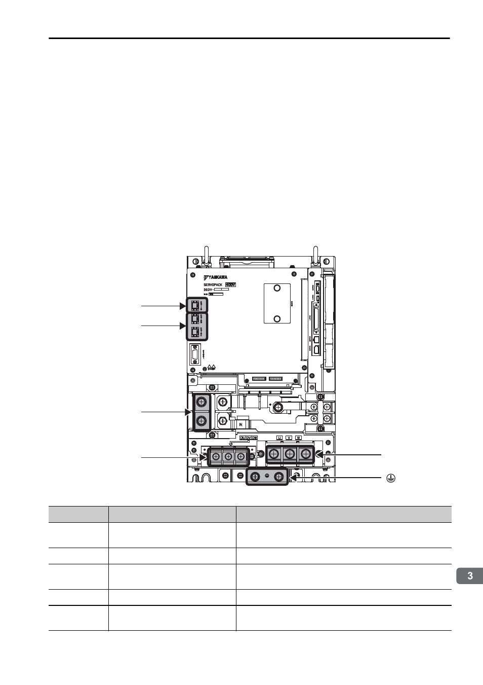
The following figure shows the appearance of the analog pulse-type SERVOPACK.
Note: For the purpose of this description, the SERVOPACK is shown with the front cover
removed. Always keep the front cover attached when using the SERVOPACK. The main
circuit terminals on the SERVOPACK are shared by all of the interfaces.
SERVOPACK
CN115
U, V, W
CN103, CN104
P, N
DU, DV, DW
Terminals
Name
Specifications
P, N
Main circuit DC voltage input
terminals
Connect these terminals to the P and N terminals on the
converter.
U, V, W
Servomotor terminals
Connect these terminals to the Servomotor terminals.
CN103,
CN104
Control power input
connectors
CN103 is the 24 VDC (
±15%) input. CN104 takes the
same input, but it is normally not necessary to connect it.
DU, DV, DW Dynamic brake unit terminals Connect these terminals to the dynamic brake unit.
CN115
Dynamic brake unit connector Connect this connector to the DBON and DB24 termi-
nals on the dynamic brake unit.