Yaskawa Sigma-5 Series User Manual:: For Use with Large-Capacity Models-Setup. Rotary Motors User Manual
Page 32
2 Installation
2.2.5 Other Precautions
2-10
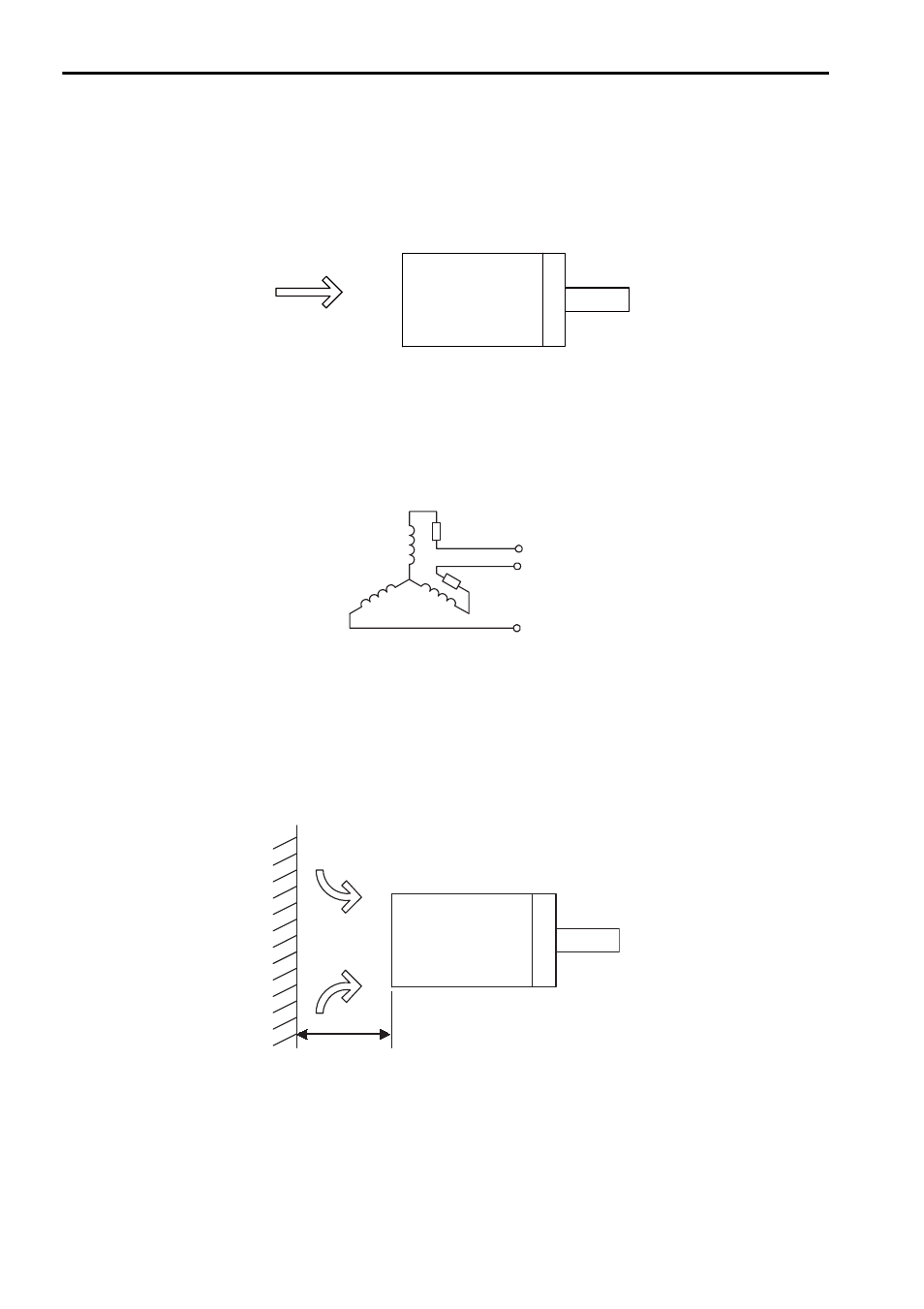
Wiring the Servomotor Fan
Wire the servomotor fan leads U(A), V(B), and W(C) so that the direction of air
flows according to the following diagram. If the air flows in the opposite direction,
change the wiring of any of the two phases U, V, and W.
Protecting the Servomotor Fan
• Protection from Overheating
The cooling fan of the servomotor has a built-in thermal protector, and the fan stops automati-
cally when excessive overheating occurs.
• Protection from Abnormal Current
Install a 2-A molded case circuit breaker on the servomotor fan cable.
Servomotor Fan Installation Space
To maximize the cooling capacity of the servomotor fan, install the fan at least 200
mm from the inlet side of the servomotor as shown in the following diagram.
Servomotor
Direction of
cooling air
U
V
W
Servomotor
Cooling air
200 mm min.