Using nc contacts for the dynamic brake contactor – Yaskawa Sigma-5 Large Capacity Users Manual: Design and Maintenance-Rotary Motors-Analog Voltage and Pulse Train Reference User Manual
Page 101
3.8 Selecting and Connecting a Dynamic Brake Unit
3-53
3
Wi
ring an
d Conn
ecti
on
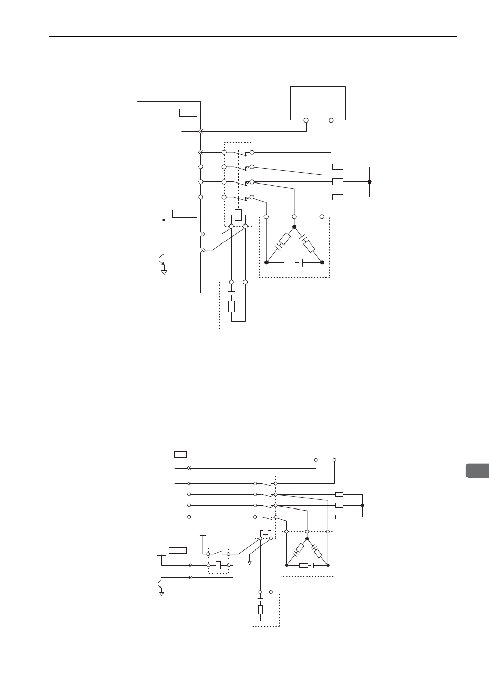
Using NC Contacts for the Dynamic Brake Contactor
∗ The above figure is for using a dynamic brake contactor with NC contacts. The dynamic brake answer signal (a signal
from NC auxiliary contacts) is input to CN1-45. To indicate an error if the input signal to CN1-45 turns OFF (open)
while the dynamic brake is activated, the Pn515 parameter in the SERVOPACK must be set to n. E
. If the
dynamic brake answer signal is not used, Pn515 is set to n. 8
(default setting).
Note 1. If you assign more than one signal to the same input circuit, OR logic will be used and any of the input signals
will cause the circuit to operate. This may result in unexpected operation.
2. The maximum current for DB24 and DBON is 300 mA.
If the coil current of NC dynamic brake contactors is 300 mA or higher, obtain an NO relay
that can switch the contactor coil current and voltage and a power supply for the contactor
coil.
DV
DU
DW
SERVOPACK
24 V
For I/O
power supply
0 V
(Auxiliary contacts)
Dynamic brake resistor
DBON
DB24
Dynamic brake contactor
Main circuit surge
absorption unit
Coil surge
absorption unit
CN115
24 V
DB
47
45*
CN1
0 V
DB
Power supply
for contactor
coil
Power supply
for contactor coil
NO relay
DV
DU
DW
SERVOPACK
For I/O
power supply
24V
0V
Dynamic brake resistor
(Auxiliary contacts)
DBON
DB24
Dynamic brake contactor
Main circuit surge
absorption unit
Coil surge
absorption unit
CN115
24V
DB
47
45
CN1
0V
DB