1) preparation, 2) operating procedure – Yaskawa Sigma-5 Large Capacity Users Manual: Design and Maintenance-Rotary Motors-Analog Voltage and Pulse Train Reference User Manual
Page 304
7.11 Manual Offset-Signal Adjustment of the Motor Current Detection Signal (Fn00F)
7-19
7
Util
ity Fu
nctions (Fn
)
7.11 Manual Offset-Signal Adjustment of the Motor Current
Detection Signal (Fn00F)
Use this function only if the torque ripple is still high after the automatic offset-signal adjustment of the motor
current detection signal (Fn00E).
Note: The adjusted value is not initialized by executing the Fn005 function (Initializing Parameter Settings).
(1) Preparation
The following condition must be met to manually adjust the offset of the motor current detection signal.
• The write prohibited setting parameter (Fn010) must be set to Write permitted (P.0000).
• The main circuit power must be ON.
• All alarms must be cleared.
• The hardwire baseblock (HWBB) must be disabled.
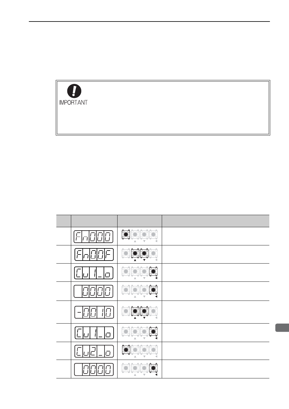
(2) Operating Procedure
Use the following procedure.
If this function is adjusted incorrectly and then executed, characteristics of the servomo-
tor performance could be affected.
Observe the following precautions when performing manual servo tuning.
• Run the servomotor at a speed of approximately 100 min
-1
.
• Adjust the offset while monitoring the torque reference with the analog monitor until
the ripple of torque reference monitor's waveform is minimized.
• Adjust the phase-U and phase-V offset amounts alternately several times until these
offsets are well balanced.
Step
Display after
Operation
Keys
Operation
1
Press the MODE/SET Key to select the utility function.
2
Press the UP or DOWN Key to select Fn00F.
3
Press the DATA/SHIFT Key for approximately one second
to adjust the phase-U offset amount. The display shown on
the left (phase U) appears.
4
Press the DATA/SHIFT Key to display the phase-U offset
amount.
5
Press the UP or DOWN Key to adjust the offset amount.
Carefully adjust the offset amount while monitoring the
torque reference monitor signal.
Adjustable range: -512 to
+
511
6
Press the DATA/SHIFT Key.
The display shown on the left appears.
7
Press the MODE/SET Key to adjust the phase-V offset
amount.
The display shown on the left (phase V) appears.
8
Press the DATA/SHIFT Key to display the phase-V offset
amount.
MODE/SET
DATA/
MODE/SET
DATA/
MODE/SET
DATA/
MODE/SET
DATA/
MODE/SET
DATA/
MODE/SET
DATA/
MODE/SET
DATA/
MODE/SET
DATA/