4 position control, Analog, Block diagram for position control – Yaskawa Sigma-5 Large Capacity Users Manual: Design and Maintenance-Rotary Motors-Analog Voltage and Pulse Train Reference User Manual
Page 153
5 Operation
5-32
5.4 Position Control
This section describes operation with position control.
Select position control with Pn000.1.
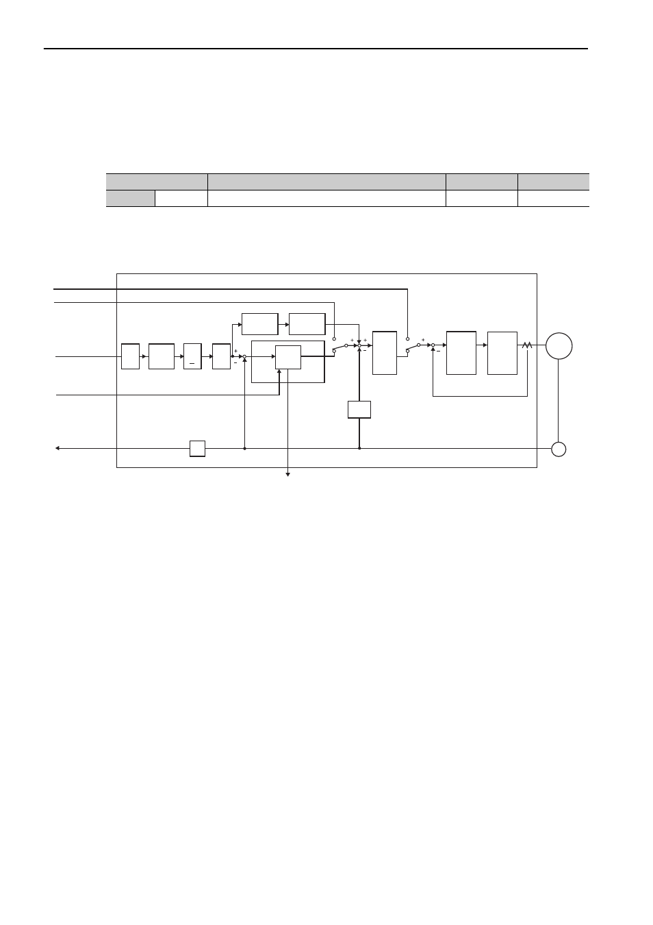
Block Diagram for Position Control
A block diagram for position control is shown below.
Parameter
Meaning
When Enabled Classification
Pn000
n.
1
Position Control
After restart
Setup
Pn10A
Error
counter
Position
control section
Position
feedback
Speed feedback
Current feedback
Torque reference
Speed reference
Clear signal input
Position reference
ENC
M
Power
amplifier
Divider
Speed
conversion
Pn000.1
Pn000.1
Pn200.0
Pn218
Pn109
Pn20E
Pn210
COIN
Pn212
Pn216
Pn217
Encoder
output pulse
SERVOPACK
Servomotor
Feed-
forward
Elec-
tronic
gear
Reference
Pulse
Multiplier
× n
Smooth-
ing
Feedforward
filter time
constant
Pn522
Positioning
completed
width
Speed
control
section
Current
control
section
B
A
Refer-
ence
pulse
form
Analog