3 setting regenerative resistor capacity, Warning – Yaskawa Sigma-5 Large Capacity Users Manual: Design and Maintenance-Rotary Motors-Analog Voltage and Pulse Train Reference User Manual
Page 94
3 Wiring and Connection
3.7.3 Setting Regenerative Resistor Capacity
3-46
3.7.3 Setting Regenerative Resistor Capacity
(1) Using a Regenerative Resistor Unit Specified by Yaskawa
Using a Specified Combination
If you use a regenerative resistor unit specified by Yaskawa in one of the specified combinations, use the fac-
tory setting for Pn600.
Using a Non-Specified Combination
If you use a non-specified combination, refer to (2) Using a Non-Specified Regenerative Resistor Unit.
(2) Using a Non-Specified Regenerative Resistor Unit
If you use a non-specified regenerative resistor unit or if you use a regenerative resistor unit specified by
Yaskawa but do not use it in the specified combination, set the capacity of the resistor in Pn600 (Regenerative
Resistor Capacity).
Be sure to set the regenerative resistor capacity (Pn600) to a value that is in accordance with the allowable
capacity of the actual regenerative resistor unit being used.
Note: If Pn600 is not set to the optimum value, alarm A.320 will occur.
The setting will vary with the cooling method of external regenerative resistor:
• For natural convection cooling: Set the value to a maximum 20% of the actually installed regenerative
resistor capacity (W).
• For forced convection cooling: Set the value to a maximum 50% of the actually installed regenerative
resistor capacity (W).
Example: Set 20 W (100 W
× 20%) for the 100-W regenerative resistor unit with natural convection
cooling method:
Pn600 = 2 (unit: 10 W)
WARNING
• If you set Pn600 to 0 when a non-specified regenerative resistor unit is connected or when a regenerative
resistor unit specified by Yaskawa is connected in a non-specified combination, regenerative overload
alarms (A.320) may not be detected. If the regenerative overload alarm (A.320) is not detected correctly,
the regenerative resistor may be damaged and an injury or fire may result. Always set Pn600 to a suitable
value.
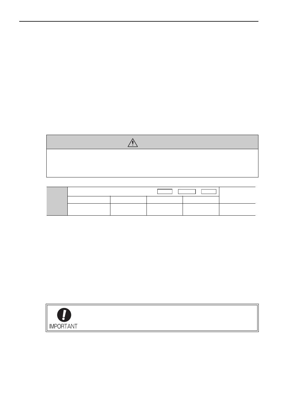
Pn600
Regenerative Resistor Capacity
Classification
Setting Range
Unit
Factory Setting
When Enabled
0 to SERVOPACK
capacity
10 W
0
Immediately
Setup
When the regenerative resistor unit for power are used at the rated load ratio, the resis-
tor temperature increases to between 200
°C and 300°C. The resistors must be used at
or below the rated values. Check with the manufacturer for the resistor’s load character-
istics.
Speed
Position
Torque