5 checking output torque limiting during operation, 64 (2) related parameters – Yaskawa Sigma-5 Large Capacity Users Manual: Design and Maintenance-Rotary Motors-Analog Voltage and Pulse Train Reference User Manual
Page 185
5 Operation
5.8.5 Checking Output Torque Limiting during Operation
5-64
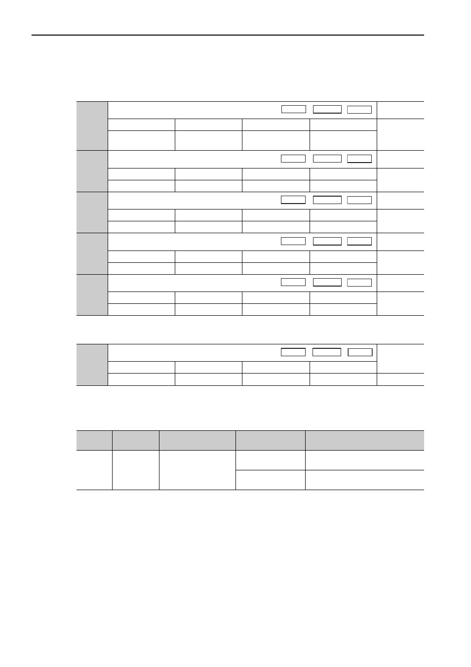
(2) Related Parameters
Set the following parameters for torque limit by external torque limit and analog voltage reference.
The setting unit is a percentage of the rated torque.
5.8.5 Checking Output Torque Limiting during Operation
The following signal can be output to indicate that the servomotor output torque is being limited.
Note: Use parameter Pn50F.0 to allocate the /CLT signal for use. For details, refer to 3.4.2 Output Signal Allocations.
Pn400
Torque Reference Input Gain
Classification
Setting Range
Setting Unit
Factory Setting
When Enabled
Setup
10 to 100
0.1 V
30 (Rated torque at
3.0 V)
Immediately
Pn402
Forward Torque Limit
Classification
Setting Range
Setting Unit
Factory Setting
When Enabled
Setup
0 to 800
1%
800
Immediately
Pn403
Reverse Torque Limit
Classification
Setting Range
Setting Unit
Factory Setting
When Enabled
Setup
0 to 800
1%
800
Immediately
Pn404
Forward External Torque Limit
Classification
Setting Range
Setting Unit
Factory Setting
When Enabled
Setup
0 to 800
1%
100
Immediately
Pn405
Reverse External Torque Limit
Classification
Setting Range
Setting Unit
Factory Setting
When Enabled
Setup
0 to 800
1%
100
Immediately
Pn415
T-REF Filter Time Constant
Classification
Setting Range
Setting Unit
Factory Setting
When Enabled
0 to 65535
0.01 ms
0
Immediately
Setup
Speed
Position
Torque
Speed
Position
Torque
Speed
Position
Torque
Speed
Position
Torque
Speed
Position
Torque
Speed
Position
Torque
Type
Signal Name
Connector
Pin Number
Setting
Meaning
Output
/CLT
Must be allocated
ON (closed)
Servomotor output torque is being lim-
ited.
OFF (open)
Servomotor output torque is not being
limited.