2 warning output signal (/warn), 1) signal specifications, 2) related parameters – Yaskawa Sigma-5 Large Capacity Users Manual: Design and Maintenance-Rotary Motors-Analog Voltage and Pulse Train Reference User Manual
Page 200
5.10 Other Output Signals
5-79
5
Ope
rat
ion
Resetting Alarms by Turning ON the /ALM-RST Signal
Resetting Alarms Using the Panel Operator
Simultaneously press the UP and the DOWN Keys on the panel operator. For details, refer to 2.1.1 Names and
Functions.
Resetting Alarms Using the Digital Operator
Press the ALARM RESET Key on the digital operator. For details, refer to
Σ
-V Series User’s Manual, Opera-
tion of Digital Operator (No.: SIEP S800000 55).
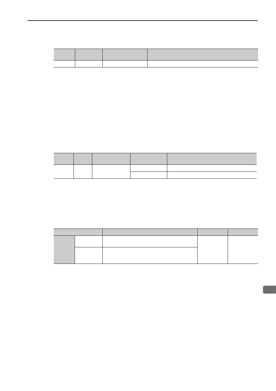
5.10.2 Warning Output Signal (/WARN)
This signal is for a warning issued before the occurrence of an alarm.
Refer to 10.2.1 List of Warnings.
(1) Signal Specifications
Note: Use parameter Pn50F.3 to allocate the /WARN signal for use. For details, refer to
3.4.2 Output Signal Alloca-
tions
.
(2) Related Parameters
Set the output method for alarm codes in Pn001.3.
For details on alarm codes, refer to (2) Alarm Code Output Signals (ALO1, ALO2, and ALO3) of 5.10.1 Servo
Alarm Output Signal (ALM) and Alarm Code Output Signals (ALO1, ALO2, and ALO3).
For details on warning codes, refer to 10.2.1 List of Warnings.
Type
Signal Name
Connector Pin
Number
Meaning
Input
/ALM-RST
CN1-44
Alarm reset
Type
Signal
Name
Connector Pin
Number
Setting
Meaning
Output
/WARN
Must be allocated
ON (closed)
Warning status
OFF (open)
Normal status
Parameter
Meaning
When Enabled Classification
Pn001
n.0
Outputs alarm codes alone for alarm codes ALO1,
ALO2, and ALO3.
After restart
Setup
n.1
Outputs both alarm and warning codes for alarm codes
ALO1, ALO2, and ALO3, and outputs an alarm code
when an alarm occurs.