2 sequence input circuit, 1) photocoupler input circuit – Yaskawa Sigma-5 Large Capacity Users Manual: Design and Maintenance-Rotary Motors-Analog Voltage and Pulse Train Reference User Manual
Page 86
3 Wiring and Connection
3.5.2 Sequence Input Circuit
3-38
3.5.2 Sequence Input Circuit
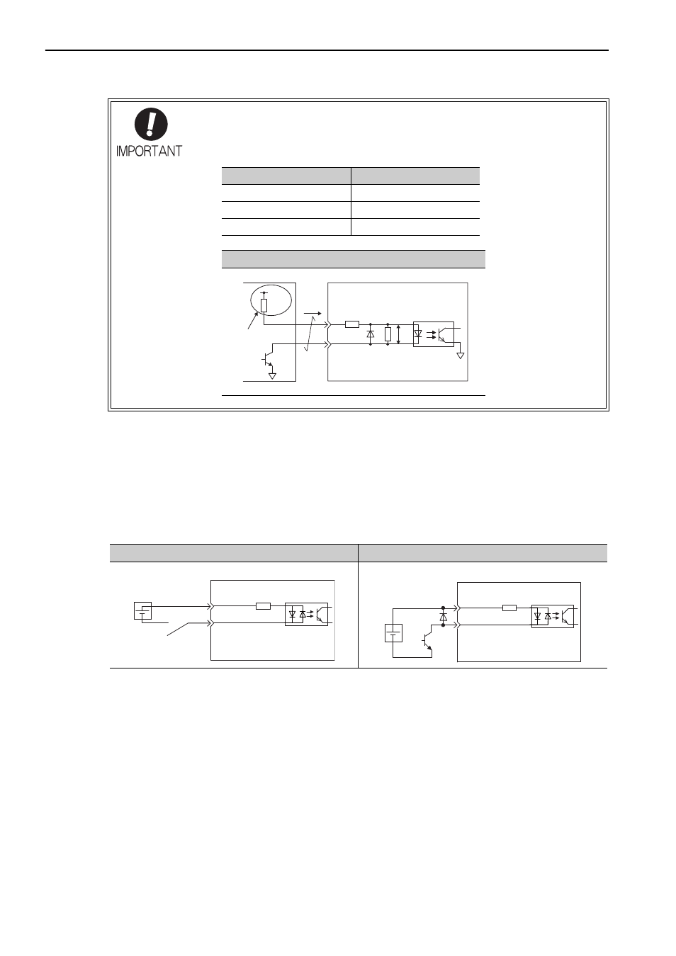
(1) Photocoupler Input Circuit
CN1 connector terminals 40 to 47 are explained below.
The sequence input circuit interface is connected through a relay or open-collector transistor circuit. When
connecting through a relay, use a low-current relay. If a low-current relay is not used, a faulty contact may
result.
Note: The 24 VDC external power supply capacity must be 50 mA minimum.
For SEN input signal circuit, refer to 5.9.2 Absolute Data Request Signal (SEN).
The SERVOPACK’s input circuit uses bidirectional photocoupler. Select either the sink circuit or the source
circuit according to the specifications required for each machine.
Note:
•
The connection examples in 3.3.3 to 3.3.5 show sink circuits.
• The ON/OFF polarity differs between when a sink circuit is connected and when a source circuit is connected.
• Precaution when host controller uses open collectors with customer-supplied power.
Before wiring, confirm that the specifications of the host controller satisfy the values
shown in the following table.
If these conditions are not satisfied, the SERVOPACK may malfunction.
Pull-up voltage (Vcc)
Pull-up resistance (R1)
24 V
1.8 to 2.7 k
Ω
12 V or less
820
Ω to 1.5 kΩ
5 V or less
180 to 470
Ω
Circuit example of open-controller output
SERVOPACK
VF = 1.5 to 1.8 V
Vcc
Tr1
VF
R1
i
Host controller
150
Ω
4.7 k
Ω
Pull-up
Relay Circuit Example
Open-collector Circuit Example
3.3 k
Ω
/S-ON, etc.
SERVOPACK
24 VDC
+24 VIN
24 VDC
3.3 k
Ω
/S-ON, etc.
SERVOPACK
+24 VIN