Yaskawa Sigma-5 Large Capacity Users Manual: Design and Maintenance-Rotary Motors-Analog Voltage and Pulse Train Reference User Manual
Page 409
11.2 List of Parameters
11-21
11
Ap
pend
ix
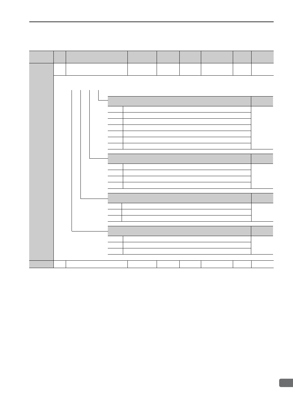
Pn200
2
Position Control Reference Form
Selection Switch
0000 to 2236
−
0000
After restart
Setup
−
Pn205
2
Multiturn Limit Setting
0 to 65535
1 rev
65535
After restart
Setup
5.9.6
(cont’d)
Parameter
No.
Size
Name
Setting
Range
Units
Factory
Setting
When Enabled Classifi-
cation
Reference
Section
Reference Pulse Form
Reference
Section
0
Sign + Pulse train, positive logic
5.4.1
1
CW + CCW pulse train, positive logic
2
Two-phase pulse train with 90
° phase differential (phase A + phase B) ×1, positive logic
3
Two-phase pulse train with 90
° phase differential (phase A + phase B) ×2, positive logic
4
Two-phase pulse train with 90
° phase differential (phase A + phase B) ×4, positive logic
5
Sign + Pulse train, negative logic
6
CW + CCW pulse train, negative logic
Clear Signal Form
Reference
Section
0
Clears position error when the signal is at high level.
5.4.2
1
Clears position error at the rising edge of the signal.
2
Clears position error when the signal is at low level.
3
Clears position error at the falling edge of the signal.
Clear Operation
Reference
Section
0
Clears position error at the baseblock (servomotor power OFF or alarm occurred).
5.4.2
1
Does not clear position error (possible to clear error counter only with CLR signal).
2
Clears position error when an alarm occurs.
Filter Selection
Reference
Section
0
Uses reference input filter 1 for line driver signal (to 1 Mpps).
5.4.1
1
Uses reference input filter for open collector signal (to 200 kpps).
2
Uses reference input filter 2 for line driver signal (1 Mpps to 4 Mpps).
4th 3rd 2nd 1st
digit digit digit digit
n.