1 basic settings for position control, 1) reference pulse form, 2) input filter selection – Yaskawa Sigma-5 Large Capacity Users Manual: Design and Maintenance-Rotary Motors-Analog Voltage and Pulse Train Reference User Manual
Page 154
5.4 Position Control
5-33
5
Ope
rat
ion
5.4.1 Basic Settings for Position Control
This section describes the basic settings for position control.
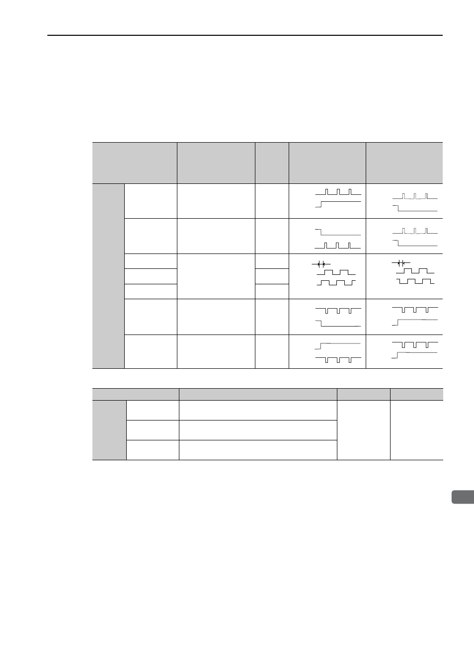
(1) Reference Pulse Form
Set the reference pulse form using Pn200.0.
(2) Input Filter Selection
Parameter
Reference Pulse
Form
Input
Pulse
Multi-
plier
Forward Run
Reference
Reverse Run
Reference
Pn200
n.
0 [Fac-
tory setting]
Sign + pulse train
(Positive logic)
−
n.
1
CW + CCW pulse train
(Positive logic)
−
n.
2
Two-phase pulse train
with 90
°
phase differen-
tial
×
1
n.
3
×
2
n.
4
×
4
n.
5
Sign + pulse train
(Negative logic)
−
n.
6
CW + CCW pulse train
(Negative logic)
−
H level
PULS
(CN1-7)
SIGN
(CN1-11)
L level
PULS
(CN1-7)
SIGN
(CN1-11)
L level
CW
(CN1-7)
CCW
(CN1-11)
L level
CW
(CN1-7)
CCW
(CN1-11)
90
ࠑ
Phase A
(CN1-7)
Phase B
1)
(CN1-1
90
ࠑ
Phase A
(CN1-7)
Phase B
1)
(CN1-1
L level
PULS
(CN1-7)
SIGN
(CN1-11)
H level
PULS
(CN1-7)
SIGN
(CN1-11)
H level
CW
(CN1-7)
CCW
(CN1-11)
H level
CW
(CN1-7)
CCW
(CN1-11)
Parameter
Meaning
When Enabled
Classification
Pn200
n.0
[Factory setting]
Uses the reference input filter for line driver signal.
(Up to 1 Mpps)
After restart
Setup
n.1
Uses the reference input filter for open-collector sig-
nal. (Up to 200 kpps)
n.2
Uses the reference input filter 2 for line driver signal.
(1 Mpps to 4 Mpps)