Yaskawa Sigma-5 Large Capacity Users Manual: Design and Maintenance-Rotary Motors-Analog Voltage and Pulse Train Reference User Manual
Page 79
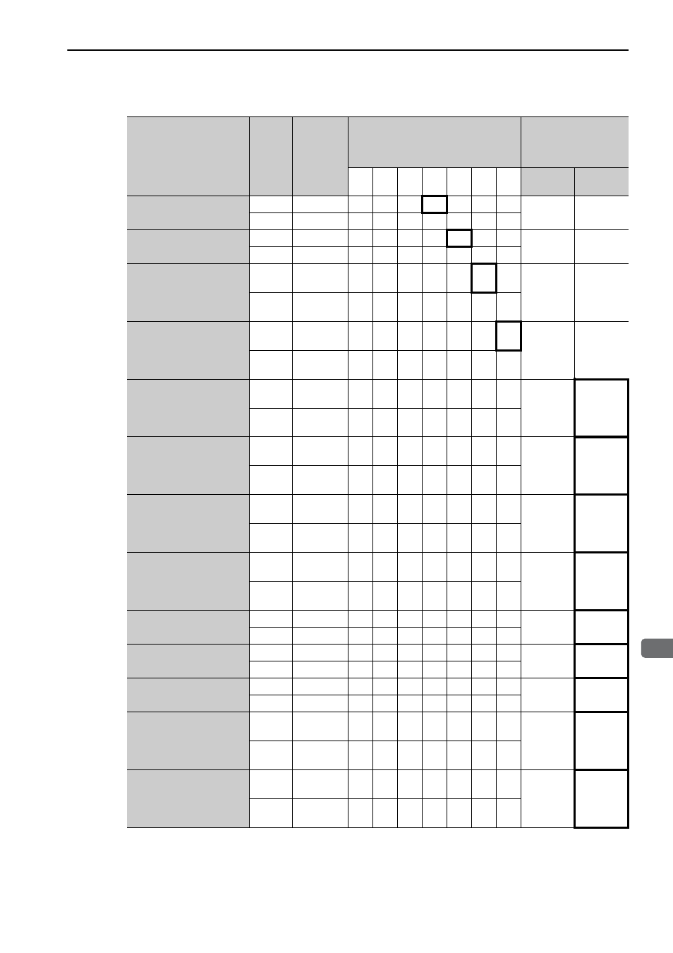
3.4 I/O Signal Allocations
3-31
3
Wi
ring an
d Conn
ecti
on
Reverse Run Prohibited
Pn50B.0
H
N-OT
0
1
2
3
4
5
6
7
8
L
/N-OT
9
A
B
C
D
E
F
Alarm Reset
Pn50B.1
L
/ARM-RST
0
1
2
3
4
5
6
–
8
H
ARM-RST
9
A
B
C
D
E
F
Forward External
Torque Limit
Pn50B.2
L
/P-CL
0
1
2
3
4
5
6
7
8
H
P-CL
9
A
B
C
D
E
F
Reverse External
Torque Limit
Pn50B.3
L
/N-CL
0
1
2
3
4
5
6
7
8
H
N-CL
9
A
B
C
D
E
F
Switching Servomotor
Rotation Direction
Pn50C.0
L
/SPD-D
0
1
2
3
4
5
6
7
8
H
SPD-D
9
A
B
C
D
E
F
Internal Set Speed
Control
Pn50C.1
L
/SPD-A
0
1
2
3
4
5
6
7
8
H
SPD-A
9
A
B
C
D
E
F
Internal Set Speed
Control
Pn50C.2
L
/SPD-B
0
1
2
3
4
5
6
7
8
H
SPD-B
9
A
B
C
D
E
F
Control Method
Selection
Pn50C.3
L
/C-SEL
0
1
2
3
4
5
6
7
8
H
C-SEL
9
A
B
C
D
E
F
Zero Clamp
Pn50D.0
L
/ZCLAMP
0
1
2
3
4
5
6
7
8
H
ZCLAMP
9
A
B
C
D
E
F
Reference Pulse Inhibit
Pn50D.1
L
/INHIBIT
0
1
2
3
4
5
6
7
8
H
INHIBIT
9
A
B
C
D
E
F
Gain Changeover
Pn50D.2
L
/G-SEL
0
1
2
3
4
5
6
7
8
H
G-SEL
9
A
B
C
D
E
F
Reference Pulse Input
Multiplication Switching
Pn515.1
L
/PSEL
0
1
2
3
4
5
6
7
8
H
PSEL
9
A
B
C
D
E
F
DB Answer
Pn515.2
L
/DBANS
0
1
2
3
4
5
6
7
8
H
DBANS
9
A
B
C
D
E
F
(cont’d)
Input Signal Names
and Parameters
Validity
Level
Input
Signal
CN1 Pin Numbers
Connection Not
Required
(SERVOPACK judges
the connection)
40
41
42
43
44
45
46
Always
ON
Always
OFF