Network load control – Pilz PSSnet SHL 8T MRP User Manual
Page 140
Network load control
PSSnet SHL - Basic Configuration
Pilz GmbH & Co. KG, Felix- Wankel Str. 2, 73760 Ostfildern
8.6 VLANs
141
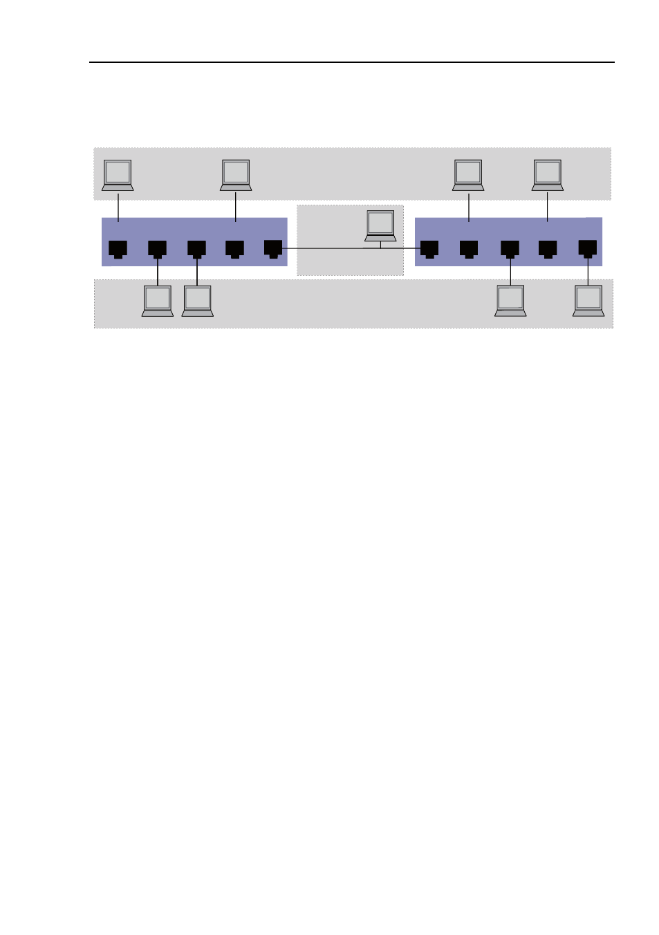
Example 2
Figure 40: Example of a more complex VLAN constellation
The second example shows a more complex constellation with 3 VLANs
(1
to
3). Along with the Switch from example 1, a second Switch (on the
right in the example) is now used.
The terminal devices of the individual VLANs (A to H) are spread over two
transmission devices (Switches). Such VLANs are therefore known as
distributed VLANs. An optional Management Station is also shown, which
enables access to all network components if it is configured correctly.
Note: In this case, VLAN 1 has no significance for the terminal device
communication, but it is required to maintain the administration of the
transmission devices via what is known as the Management VLAN.
As in the previous example, uniquely assign the ports with their connected
terminal devices to a VLAN. With the direct connection between the two
transmission devices (uplink), the ports transport packets for both VLANs.
To differentiate these, “VLAN tagging” is used, which prepares the pack-
ets accordingly
(see on page
119
„VLAN
tagging“)
. This ensures that the
assignments to the respective VLANs is maintained.
Proceed as follows to perform the example configuration:
Add Uplink Port 5 to the ingress and egress tables from example 1. Cre-
ate new ingress and egress tables for the right switch, as described in the
first example.
The egress table specifies to which VLAN the frames sent from this port
are assigned. Your entry also defines whether Ethernet frames sent from
this port are to be tagged:
1
3
2
VLAN
2
VLAN
3
A
B
C
D
1
4
3
2
E
F
H
G
4
5
5
Management
Station (optional)
VLAN 1