Physical layer buffer status signals, Transceiver signals, Table 5–8 on – Altera RapidIO MegaCore Function User Manual
Page 118
5–4
Chapter 5: Signals
Physical Layer Signals
RapidIO MegaCore Function
August 2014
Altera Corporation
User Guide
Physical Layer Buffer Status Signals
Transceiver Signals
Table 5–8
lists the transceiver signals. These signals are connected directly to the
transceiver block. In some cases these signals must be shared by multiple transceiver
blocks that are implemented in the same device.
Table 5–9
lists the Arria 10 Native PHY dynamic reconfiguration interface signals.
Each of these individual interfaces is an Avalon-MM interface you use to access the
hard registers for the corresponding transceiver channel on the Arria 10 device. These
signals are available if you turn on Enable transceiver dynamic reconfiguration in
the RapidIO parameter editor.
buf_av3
Output
Buffers available for priority 3 retry packets.
yes
Note to
(1) All of these signals are in the sysclk domain.
Table 5–6. Priority Retry Threshold Signals
(1)
(Part 2 of 2)
Signal
Direction
Description
Exported by
Qsys
Table 5–7. Physical Layer Buffer Status Signals
Signal
Direction
Description
atxwlevel
(2)
Output
Transmit buffer write level (number of free 64-byte blocks in the transmit buffer).
atxovf
Output
Transmit buffer overflow.status.
arxwlevel
(2)
Output
Receive buffer write level (number of free 64-byte blocks in the receive buffer).
Notes to
Table 5–7
:
(1) All of these signals are in the sysclk domain.
(2) The formula log
2
(size
of the transmit/receive buffer in bytes/64)+1 determines the width of this signal in bits. For example, a
transmit or receive buffer size of 16 KBytes would give: log
2
(16×1024/64)+1=
9 bits (for example, [8:0]).
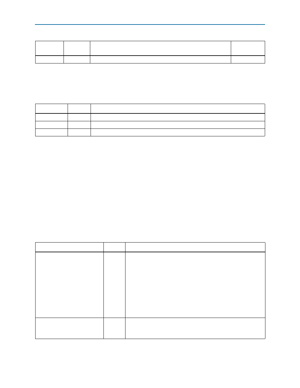
Table 5–8. Transceiver Signals (Part 1 of 4)
Signal Direction
Description
cal_blk_clk
(1)
Input
The Arria II GX, Arria II GZ, Cyclone IV GX, and Stratix IV GX transceiver’s
on-chip termination resistors are calibrated by a single calibration block.
This circuitry requires a calibration clock. The frequency range of the
cal_blk_clk
is 10–125 MHz. For more information, refer to the
n volume 2 of the
Arria II Device Handbook, the
chapter
in volume 2 of the Cyclone IV Device Handbook, or th
chapter in volume 2 of the Stratix IV Device
Handbook.
This signal is not present in Arria V, Arria 10, Cyclone V, or Stratix V
variations.
phy_mgmt_clk
(1)
Input
Clocks the Custom PHY IP core software interface. The expected
maximum frequency of this clock is 250 MHz.
This signal is present only in Arria V, Cyclone V, and Stratix V variations.