Avalon-st pass-through interface signals, Avalon-st pass-through interface signals –13, Table 5–18 – Altera RapidIO MegaCore Function User Manual
Page 127
Chapter 5: Signals
5–13
Transport and Logical Layer Signals
August 2014
Altera Corporation
RapidIO MegaCore Function
User Guide
Avalon-ST Pass-Through Interface Signals
through
list the standard Avalon-ST pass-through interface
signals.
1
When you instantiate the IP core with Qsys, these signals are automatically connected
and are not visible as inputs or outputs of the system.
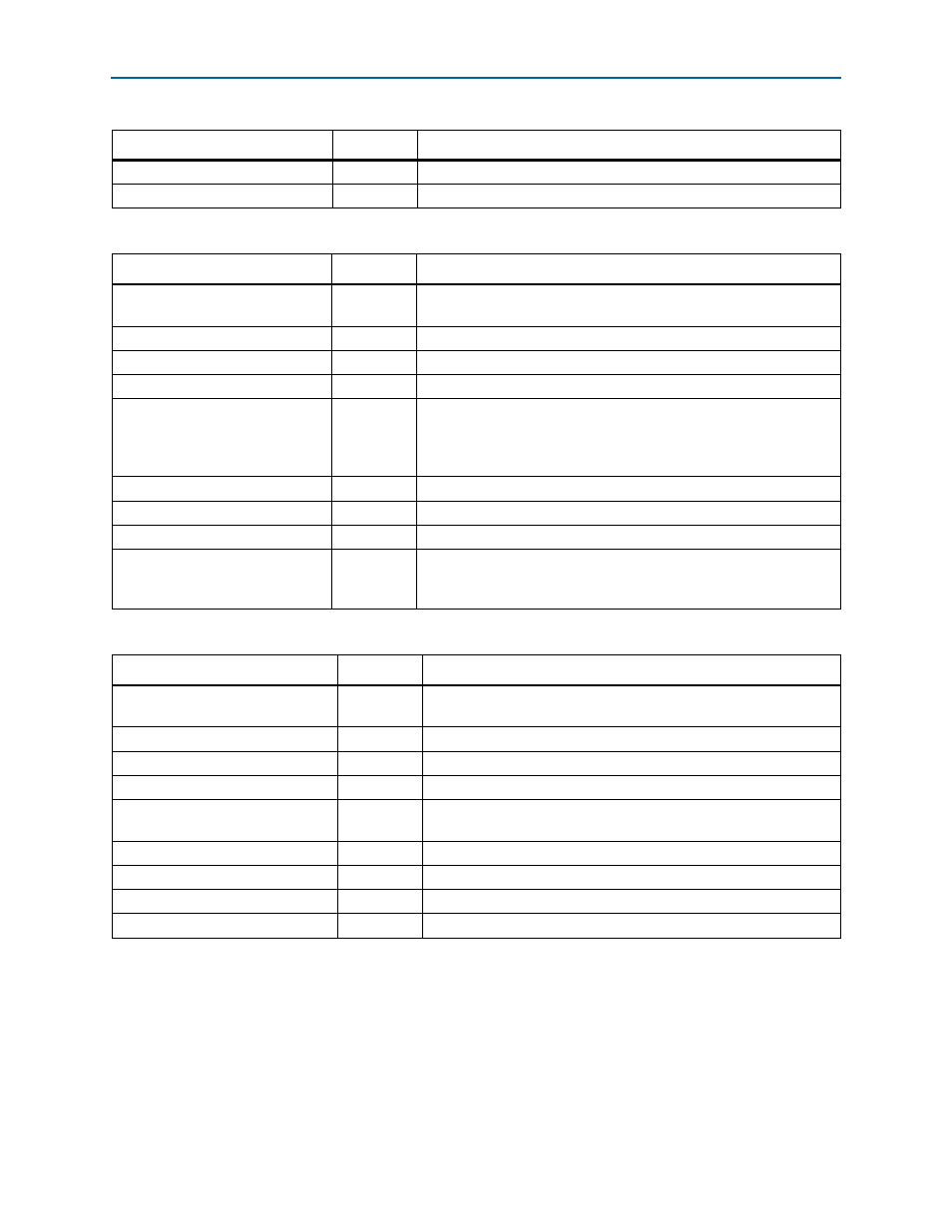
io_s_wr_byteenable[m:0]
Input
Input/Output slave byte enable.
io_s_wr_burstcount[k:0]
Input
Input/Output slave burst count.
Table 5–16. Input/Output Slave Datapath Write Avalon-MM Interface Signals (Part 2 of 2)
Signal
Direction
Description
Table 5–17. Input/Output Slave Datapath Read Avalon-MM Interface Signals
Signal
Direction
Description
io_s_rd_clk
Input
This signal is not used, therefore it can be left open. The Avalon clock is
used internally as the clock reference for this interface.
io_s_rd_chipselect
Input
Input/Output slave chip select.
io_s_rd_waitrequest
Output
Input/Output slave wait request.
io_s_rd_read
Input
Input/Output slave read enable.
io_s_rd_address[j:0]
Input
Input/Output slave address bus. In 1x variations, this address is a word
address (addresses a 4-byte (32-bit) word), not a byte address. In 2x
and 4x variations, this address is a double-word address (addresses an
8-byte (64-bit) word).
io_s_rd_readdata[n:0]
Output
Input/Output slave read data bus.
io_s_rd_readdatavalid
Output
Input/Output slave read data valid.
io_s_rd_burstcount[k:0]
Input
Input/Output slave burst count.
io_s_rd_readerror
Output
Input/Output slave read error indicates that the burst read transfer did
not complete successfully. This signal is valid only when the
io_s_rd_readdatavalid
signal is asserted.
Table 5–18. Doorbell Message Avalon-MM Slave Interface Signals
Signal
Direction
Description
drbell_s_clk
Input
This signal is not used, therefore it can be left open. The Avalon clock
is used internally as the clock reference for this interface.
drbell_s_chipselect
Input
Doorbell chip select
drbell_s_write
Input
Doorbell write enable
drbell_s_read
Input
Doorbell read enable
drbell_s_address[3:0]
Input
Doorbell address bus. This address is a word address (addresses a 4-
byte (32-bit) word), not a byte address.
drbell_s_writedata[31:0]
Input
Doorbell write data bus
drbell_s_readdata[31:0]
Output
Doorbell read data bus
drbell_s_waitrequest
Output
Doorbell wait request
drbell_s_irq
Output
Doorbell interrupt