Altera RapidIO MegaCore Function User Manual
Page 126
5–12
Chapter 5: Signals
Transport and Logical Layer Signals
RapidIO MegaCore Function
August 2014
Altera Corporation
User Guide
■
j = ((I/O slave address width minus N) - 1) — the I/O slave address width value is
defined in the RapidIO parameter editor. N is 2 for 1x variations and 3 for 2x and
4x variations.
The internal datapath width is 32 bits in RapidIO 1x variations, and 64 bits in RapidIO
2x and 4x variations.
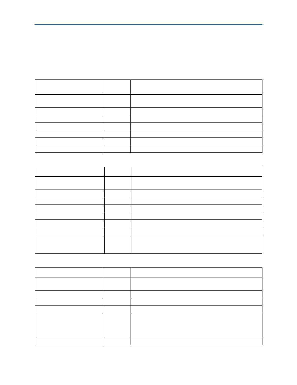
Table 5–14. Input/Output Master Datapath Write Avalon-MM Interface Signals
Signal
Direction
Description
io_m_wr_clk
Input
This signal is not used, therefore it can be left open. The Avalon clock
is used internally as the clock reference for this interface.
io_m_wr_waitrequest
Input
Input/Output master wait request.
io_m_wr_write
Output
Input/Output master write enable.
io_m_wr_address[31:0]
Output
Input/Output master address bus.
io_m_wr_writedata[n:0]
Output
Input/Output master write data bus.
io_m_wr_byteenable[m:0]
Output
Input/Output master byte enable.
io_m_wr_burstcount[k:0]
Output
Input/Output master burst count.
Table 5–15. Input/Output Master Datapath Read Avalon-MM Interface Signals
Signal
Direction
Description
io_m_rd_clk
Input
This signal is not used, therefore it can be left open. The Avalon clock
is used internally as the clock reference for this interface.
io_m_rd_waitrequest
Input
Input/Output master wait request.
io_m_rd_read
Output
Input/Output master read enable.
io_m_rd_address[31:0]
Output
Input/Output master address bus.
io_m_rd_readdata[n:0]
Input
Input/Output master read data bus.
io_m_rd_readdatavalid
Input
Input/Output master read data valid.
io_m_rd_burstcount[k:0]
Output
Input/Output master burst count.
io_m_rd_readerror
Input
Input/Output master indicates that the burst read transfer did not
complete successfully. This signal should be asserted through the
final cycle of the read transfer.
Table 5–16. Input/Output Slave Datapath Write Avalon-MM Interface Signals (Part 1 of 2)
Signal
Direction
Description
io_s_wr_clk
Input
This signal is not used, therefore it can be left open. The Avalon clock
is used internally as the clock reference for this interface.
io_s_wr_chipselect
Input
Input/Output slave chip select.
io_s_wr_waitrequest
Output
Input/Output slave wait request.
io_s_wr_write
Input
Input/Output slave write enable.
io_s_wr_address[j:0]
Input
Input/Output slave address bus. In 1x variations, this address is a word
address (addresses a 4-byte (32-bit) word), not a byte address. In 2x
and 4x variations, this address is a double-word address (addresses an
8-byte (64-bit) word).
io_s_wr_writedata[n:0]
Input
Input/Output slave write data bus.