Input/output master address mapping registers, Input/output master address mapping registers –20, Table 6–38 – Altera RapidIO MegaCore Function User Manual
Page 152
6–20
Chapter 6: Software Interface
Transport and Logical Layer Registers
RapidIO MegaCore Function
August 2014
Altera Corporation
User Guide
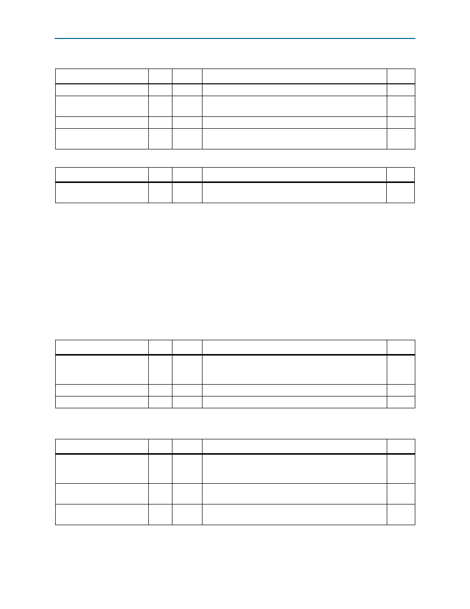
Input/Output Master Address Mapping Registers
through
describe the Input/Output master registers. When the
IP core receives an NREAD, NWRITE, NWRITE_R, or SWRITE request packet, the RapidIO
address has to be translated into a local Avalon-MM address. The translation involves
the base, mask, and offset registers. There are up to 16 register sets, one for each
address mapping window. The 16 possible register address offsets are shown in the
table titles.
Refer to
“Input/Output Avalon-MM Master Address Mapping Windows” on
for more details.
Table 6–37. Rx Port Write Status—Offset: 0x10254
Field
Bits
Access
Function
Default
RSRV
[31:6] RO
Reserved
26'h0
PAYLOAD_SIZE
[5:2]
RO
Packet payload size in number of double words. If the size is
zero, the payload size is single word.
4'h0
RSRV
[1]
RO
Reserved
1'b0
PORT_WRITE_BUSY
[0]
RO
Port-write busy. Set if a packet is currently being stored in the
buffer or if the packet is stored and has not been read.
1'b0
Table 6–38. Rx Port Write Buffer n—Offset: 0x10260 – 0x1029C
Field
Bits
Access
Function
Default
PORT_WRITE_DATA_n
[31:0] RO
Port-write data. This buffer is implemented in memory and is
not initialized at reset.
32'hx
Table 6–39. Input/Output Master Mapping Window n Base—Offset: 0x10300, 0x10310, 0x10320, 0x10330, 0x10340,
0x10350, 0x10360, 0x10370, 0x10380, 0x10390, 0x103A0, 0x103B0, 0x103C0, 0x103D0, 0x103E0, 0x103F0
Field
Bits
Access
Function
Default
BASE
[31:3] RW
Start of the RapidIO address window to be mapped. The three
least significant bits of the 34-bit base are assumed to be
zeros.
29'h0
RSRV
[2]
RO
Reserved
1'b0
XAMB
[1:0]
RW
Extended Address: two most significant bits of the 34-bit base. 2'h0
Table 6–40. Input/Output Master Mapping Window n Mask—Offset: 0x10304, 0x10314, 0x10324, 0x10334, 0x10344,
0x10354, 0x10364, 0x10374, 0x10384, 0x10394, 0x103A4, 0x103B4, 0x103C4, 0x103D4, 0x103E4, 0x103F4
Field
Bits
Access
Function
Default
MASK
[31:3] RW
Bits 31 to 3 of the mask for the address mapping window. The
three least significant bits of the 34-bit mask are assumed to
be zeros.
29'h0
WEN
[2]
RW
Window enable. Set to one to enable the corresponding
window.
1'b0
XAMM
[1:0]
RW
Extended Address: two most significant bits of the 34-bit
mask.
2’b0