Televes Serie H-60 User Manual
Page 123
123
EN
3.3.3.2.3.- RF attenuation
The RF attenuation function allows us to measure theattenuation that exists in a facility.
Can be set between 5 and 10 frequencies (frequency range: 5MHz to 2200MHz) in each of which will
measure the attenuation. For this purpose, shall select the number of frequencies to be measured
with the button "FREQUENCY NUMBER”; and frequency values to be measured with the button
"FREQUENC."
Once selected the frequencies, we must connect the meter at the point in respect of which we want
measure the attenuation (usually, at the output of the headend of the installation) and press the
button "CALIBRATE". The equipment will measure the level in each of the selected frequencies
previously, and will memorize its value.
Then we can move to each of the points (outlets) where we want to measure the attenuation and
connect the meter. The equipment will measure the level in each of the outlets, and plot the
attenuation (relative to the measurement made in the previous stage CALIBRATE) in each of the
frequencies.
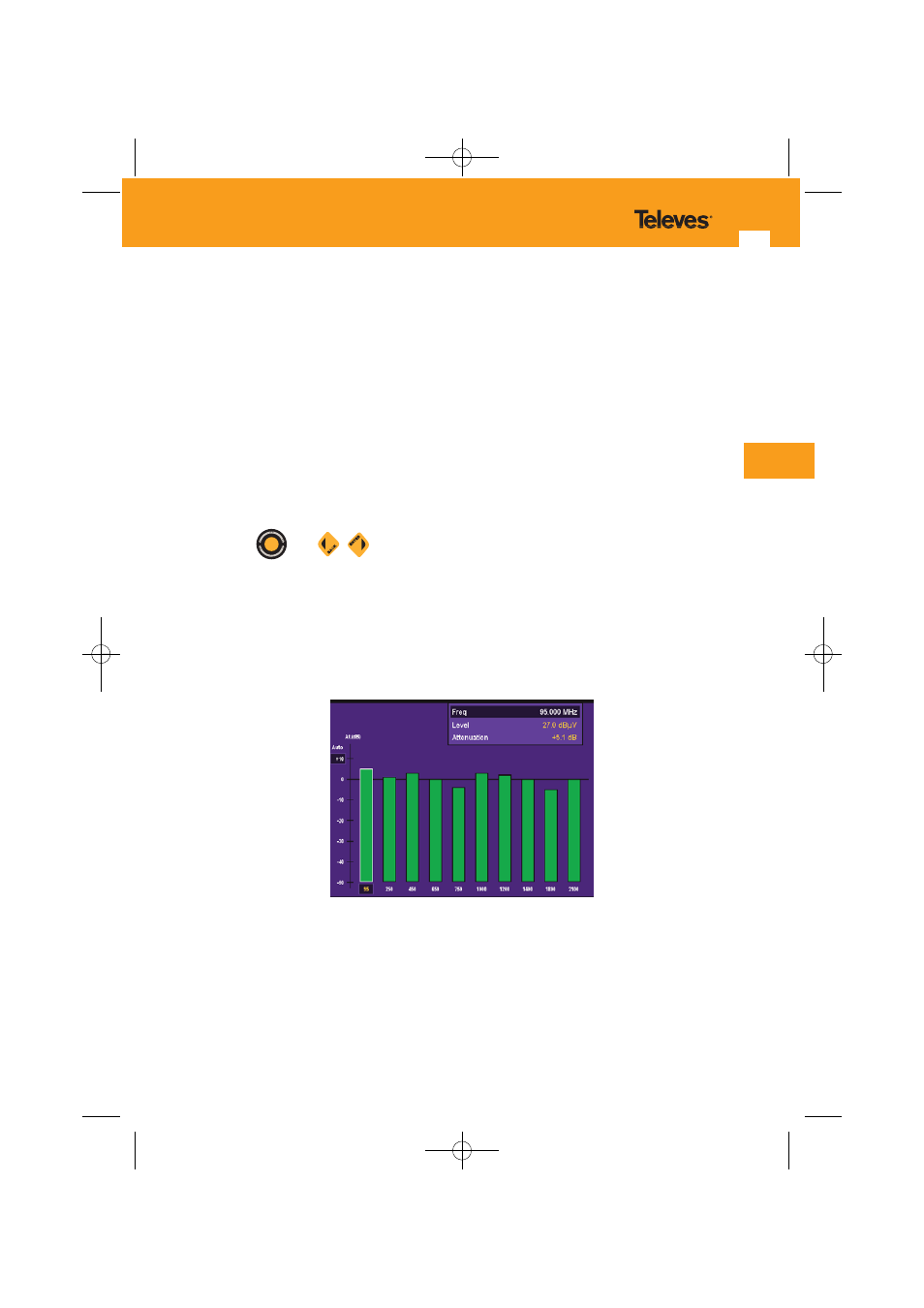
Through
and
, we can select each of the channels in which the attenuation is
measured, showing in the upper box the frequency, level, and the attenuationregarding the
measurement on the calibration stage.
We can configure various aspects of the graphic representation of the attenuation:
- VISUALIZATION MODE: With this button you can choose two modes of representation:
- Mode 1: In this mode, the attenuation is always displayed by a bar growing from the bottom
of the screen; showing, graphically, the existing attenuation at each frequency.
- Visualization of attenuation. Mode 1 -
- Mode 2: In this mode the attenuation is shown with abar increasing or decreasing from the
axis of 0 dB.Thus, you will see if, for a certain frequency, we have attenuation (if
the bar decreases from 0 dB) or amplification (the bar increases from 0 dB).
01031052_002_EN:103130_00.qxd 10/07/2013 8:00 Página 123