Standard ext, Calibration – BECKHOFF EL7037 User Manual
Page 148
Commissioning
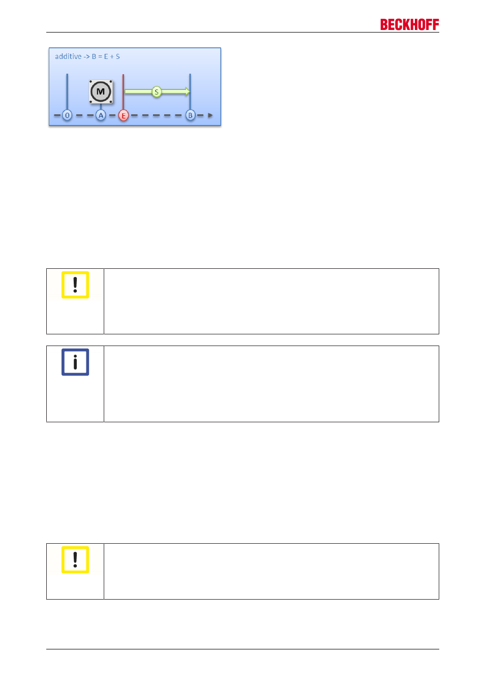
Fig. 170: Additive positioning
ABSOLUTE_CHANGE / RELATIVE_CHANGE / ADDITIVE_CHANGE:
These three kinds of positioning are completely identical to those described above. The important difference
thereby is that the user uses these commands during an active travel command in order to dynamically
specify a new target position.
The same rules and conditions apply as to the “normal” start types. “ABSOLUTE_CHANGE” and
“ADDITIVE_CHANGE” are unique in the calculation of the target position i.e. in absolute positioning an
absolute position is specified and in additive positioning a position delta is added to the momentarily active
target position.
Attention
Caution when using the “RELATIVE_CHANGE” positioning
The change by means of "RELATIVE_CHANGE" must be used with caution, since the cur-
rent position of the motor is also used here as the start position. Due to propagation delays
in the system, the position indicated in the PDO never corresponds to the actual position of
the motor! Therefore a difference to the desired target position always results in the calcu-
lation of the transferred position delta.
Note
Time of the change of the target position
A change of the target position cannot take place at an arbitrary point in time. If the calcula-
tion of the output parameters shows that the new target position cannot be readily reached,
the command is rejected by the terminal and the “Command rejected [
143]” bit is set. This
is the case, for example, at standstill (since the terminal expects a standard positioning
here) and in the acceleration phase (since at this point the braking time cannot be calcu-
lated yet).
CALI_PLC_CAM / CALI_HW_SYNC / SET_CALIBRATION /
SET_CALIBRATION_AUTO / CLEAR_CALIBRATION:
The simplest calibration case is calibration by cam only (connected to one digital input).
Here, the motor travels in the 1
st
step with velocity 1 (Index 8020:09 [
183]) in direction 1 (Index 8021:13
184]) towards the cam. Subsequently, in the 2
nd
step, it travels with velocity 2 (Index 8020:0A [
183]) in
direction 2 (Index 8021:14 [
184]) away from the cam. After the "In-Target timeout" (Index 8020:0C [
has elapsed, the calibration position (Index 8020:08 [
183]) is taken on by the terminal as the current
position.
Attention
Observe the switching hysteresis of the cam switch
With this simple calibration it must be noted that the position detection of the cam is only
exact to a certain degree. The digital inputs are not interrupt-controlled and are “only”
polled. The internal propagation delays may therefore result in a system-related position
difference.
EL70x7
148
Version 1.0