2 el7037 - general connection examples, Connection examples – BECKHOFF EL7037 User Manual
Page 50
Installation
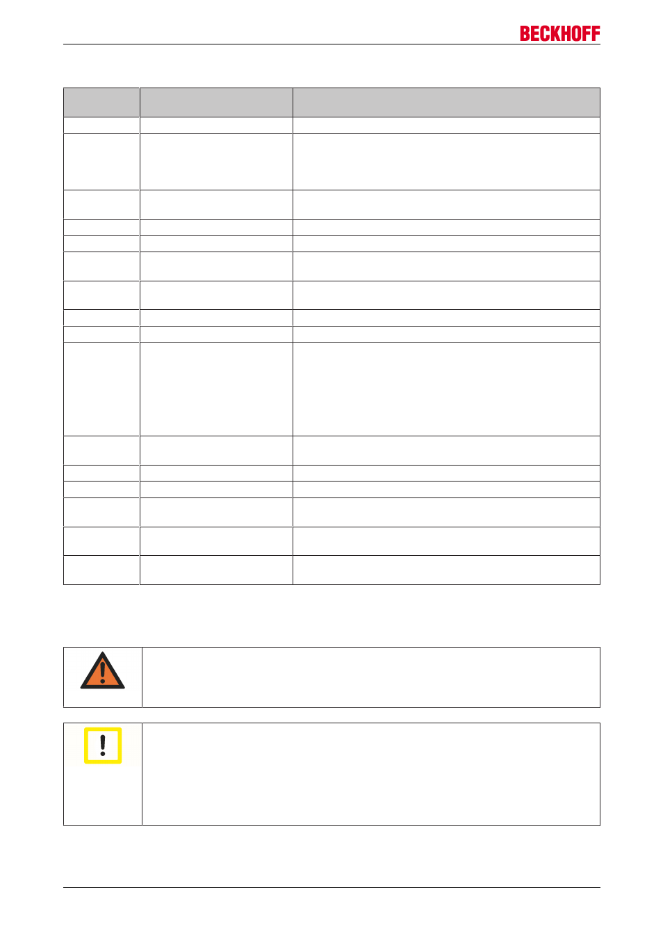
Terminal points
Terminal
point
Name
Signal
1
A
Encoder input A
2
C
Encoder input C (zero input). If object 7000:01 [
the control word and a rising edge occurs at encoder input C,
the current counter value is stored as a reference mark in the
latch register.
3
Encoder supply
+24V
Encoder supply + 24 V, internally connected with positive
power contact and pin 6, 7
4
A1
Motor winding A1
5
B1
Motor winding B1
6
+24V
+24 V
DC
, internally connected with positive power contact and
pin 3, 7
7
+24V
+24 V
DC
, internally connected with positive power contact and
pin 3, 7
8
Input 1
Digital input 1 (24 V
DC
)
9
B
Encoder input B
10
Latch
Latch input. The current counter value is stored as a
reference mark in the latch register, if
• object 7000:02 [
186] is set and a rising edge occurs at
the latch input; or
• object 7000:04 [
186] is set and a falling edge occurs
at the latch input.
11
Encoder supply
0V
Encoder supply 0 V, internally connected with negative power
contact and pin 14, 15
12
A2
Motor winding A2
13
B2
Motor winding B2
14
0V
0 V
DC
, internally connected with negative power contact and
pin 11, 15
15
0V
0 V
DC
, internally connected with negative power contact and
pin 11, 14
16
Input 2
Digital input 2 (24 V
DC
), also configurable as a digital output
(0,5 A)
4.6.2
EL7037 - General connection examples
WARNING
Risk of injury through electric shock and damage to the device!
Bring the Bus Terminal system into a safe, de-energized state before starting mounting,
disassembly or wiring of the Bus Terminals.
Attention
Connect the motor strands correctly!
Connect the windings of a motor strand only to the terminal points of the same output driver
of the stepper motor terminal, e.g.:
• one motor strand to terminal points A1 and A2,
• the other motor strand to terminal points B1 and B2.
Connecting a motor strand to the terminal points of different output drivers (e.g. to A1 and
B1) can lead to destruction of the output drivers of stepper motor terminal!
EL70x7
50
Version 1.0