BECKHOFF EL7037 User Manual
Page 39
Installation
Disassembly
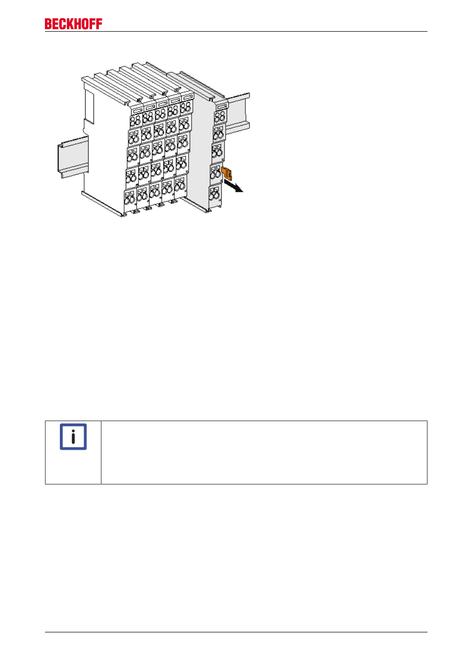
Fig. 25: Disassembling of terminal
Each terminal is secured by a lock on the mounting rail, which must be released for disassembly:
1. Pull the terminal by its orange-colored lugs approximately 1 cm away from the mounting rail. In doing
so for this terminal the mounting rail lock is released automatically and you can pull the terminal out of
the bus terminal block easily without excessive force.
2. Grasp the released terminal with thumb and index finger simultaneous at the upper and lower grooved
housing surfaces and pull the terminal out of the bus terminal block.
Connections within a bus terminal block
The electric connections between the Bus Coupler and the Bus Terminals are automatically realized by
joining the components:
• The six spring contacts of the K-Bus/E-Bus deal with the transfer of the data and the supply of the Bus
Terminal electronics.
• The power contacts deal with the supply for the field electronics and thus represent a supply rail within
the bus terminal block. The power contacts are supplied via terminals on the Bus Coupler (up to 24 V)
or for higher voltages via power feed terminals.
Note
Power Contacts
During the design of a bus terminal block, the pin assignment of the individual Bus Termi-
nals must be taken account of, since some types (e.g. analog Bus Terminals or digital 4-
channel Bus Terminals) do not or not fully loop through the power contacts. Power Feed
Terminals (KL91xx, KL92xx or EL91xx, EL92xx) interrupt the power contacts and thus rep-
resent the start of a new supply rail.
PE power contact
The power contact labeled PE can be used as a protective earth. For safety reasons this contact mates first
when plugging together, and can ground short-circuit currents of up to 125 A.
EL70x7
39
Version 1.0