Yaskawa P7B Drive Bypass User Manual
Page 100
Programming 5 - 6
"
Options - P "Pneumatic Pressure Transducer"; Bypass with pneumatic input for speed
control:
Hand mode speed command from Keypad/Operator.
Auto mode speed command input signal from the pneumatic transducer, or 4-20 mA applied to Drive terminal A2.
Auto mode run/stop contact closure for Drive and Bypass applied to terminals TB1-3 and TB1-4.
"
Options - P and S "Pneumatic Pressure Transducer" and "Speed Pot."; Bypass with pneumatic
input and speed potentiometer for speed control:
Hand mode speed command from speed potentiometer.
Auto mode speed command input signal from the pneumatic transducer, or 4-20 mA applied to Drive terminal A2.
Auto mode run/stop contact closure for Drive and Bypass applied to terminals TB1-3 and TB1-4.
"
Options - S "Speed Pot."; Bypass with speed potentiometer for speed control:
Hand mode speed command from speed potentiometer.
Auto mode speed command input signal, 4-20 mA applied to Drive terminal A2.
Auto mode run/stop contact closure for Drive and Bypass applied to terminals TB1-3 and TB1-4.
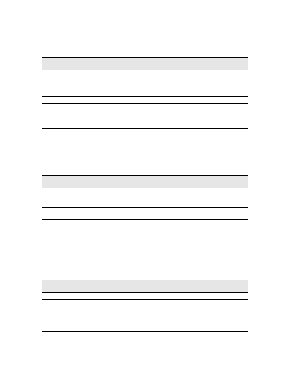
Significant
Parameter Setting
Result
b1-01 = 1: Terminals (default)
Speed command source = Terminals
H3-13 = 1: Main Fref TA2
Specific speed command source = Terminal A2
H3-08 = 2: 4-20 mA (default)
Terminal A2 is programmed for 4-20 mA (Transducer output is 4-20 mA) (Note
– Control PCB DIP switch S1-2 must also be ON)
H3-02 = 0.0
Terminal A1 gain = 0.0 (To insure no stray signal level at this unused terminal)
H3-09 = 0: Frequency Bias
Terminal A2 function is set to “bias” the terminal A1 input. Terminal A1 is not
used, therefore the A2 “bias” signal becomes the speed command.
H1-03 = 3: Multi-Step Ref 1
(default)
A terminal S5 input contact closure selects d1-02 (keypad) as a preset speed.
This input contact is closed when H/O/A = Hand.
Significant
Parameter Setting
Result
b1-01 = 1: Terminals (default)
Speed command source = Terminals
H3-13 = 1: Main Fref TA2
Main speed command source = Terminal A2 and the Aux speed command source
= Terminal A1
H3-08 = 2: 4-20 mA (default)
Terminal A2 is programmed for 4-20 mA (Transducer output is 4-20 mA) (Note
– Control PCB DIP switch S1-2 must also be ON)
H3-09 = 2: Aux Reference (default) Aux Terminal (A1) function is set to be a speed command input.
H1-03 = 3: Multi-Step Ref 1
(default)
A terminal S5 input contact closure selects Aux Terminal (A1) as a preset speed.
This input contact is closed when H/O/A = Hand.
Significant
Parameter Setting
Result
b1-01 = 1: Terminals (default)
Speed command source = Terminals
H3-13 = 1: Main Fref TA2
Main speed command source = Terminal A2 and the Aux speed command source
= Terminal A1
H3-08 = 2: 4-20 mA (default)
Terminal A2 is programmed for 4-20 mA (Note – Control PCB DIP switch S1-2
must also be ON)
H3-09 = 2: Aux Reference (default) Aux Terminal (A1) function is set to be a speed command input.
H1-03 = 3: Multi-Step Ref 1
(default)
A terminal S5 input contact closure selects Aux Terminal (A1) as a preset speed.
This input contact is closed when H/O/A = Hand.