Yaskawa P7B Drive Bypass User Manual
Page 24
Physical Installation 1 - 12
"
HAND/OFF/AUTO Selector Switch
A three position rotary switch employed to control the source of the motor start and speed commands in either the Drive or
Bypass operating modes.
Hand Position – Drive Mode: The Drive input and output contactors are energized and the Drive is given a run command.
Operation is via the local speed input from the keypad or optional speed potentiometer.
Hand Position – Bypass Mode: The Bypass contactor is energized causing the motor to run at full speed directly across-the-
line.
Off Position: No power is applied to the Bypass circuit. The Drive input and output contactors are energized and the Drive is
stopped (run command removed). The Off position takes precedence over a serial communication run command.
Auto Position – Drive Mode: The Drive input and output contactors are energized. The Drive is enabled to receive a run
command contact closure and speed input analog signal from a separate source.
Auto Position – Bypass Mode: The motor full speed across-the-line run/stop is controlled by a customer supplied contact
closure, energizing the Bypass contactor.
The H/O/A switch must be in the AUTO position if serial communication is to be used for Drive run, stop and speed control.
"
DRIVE/BYPASS Selector Switch
A two position rotary switch selecting motor operation from the Drive or directly across-the-line. When transferring from
Drive operation to Bypass operation, the logic circuit will require the Bypass unit to stop the motor before completing the
transfer to full speed across-the-line operation.
"
NORMAL/TEST Selector Switch
A two position rotary switch, test position is used to energize the Drive input contactor while operating in the Bypass mode
(via the HAND or AUTO switch position). In Drive mode switching from NORMAL to TEST position will remove the
power from the Drive and the motor will stop. In Bypass mode the test position powers the Drive for programming or other
“tests” while keeping it isolated from the motor.
"
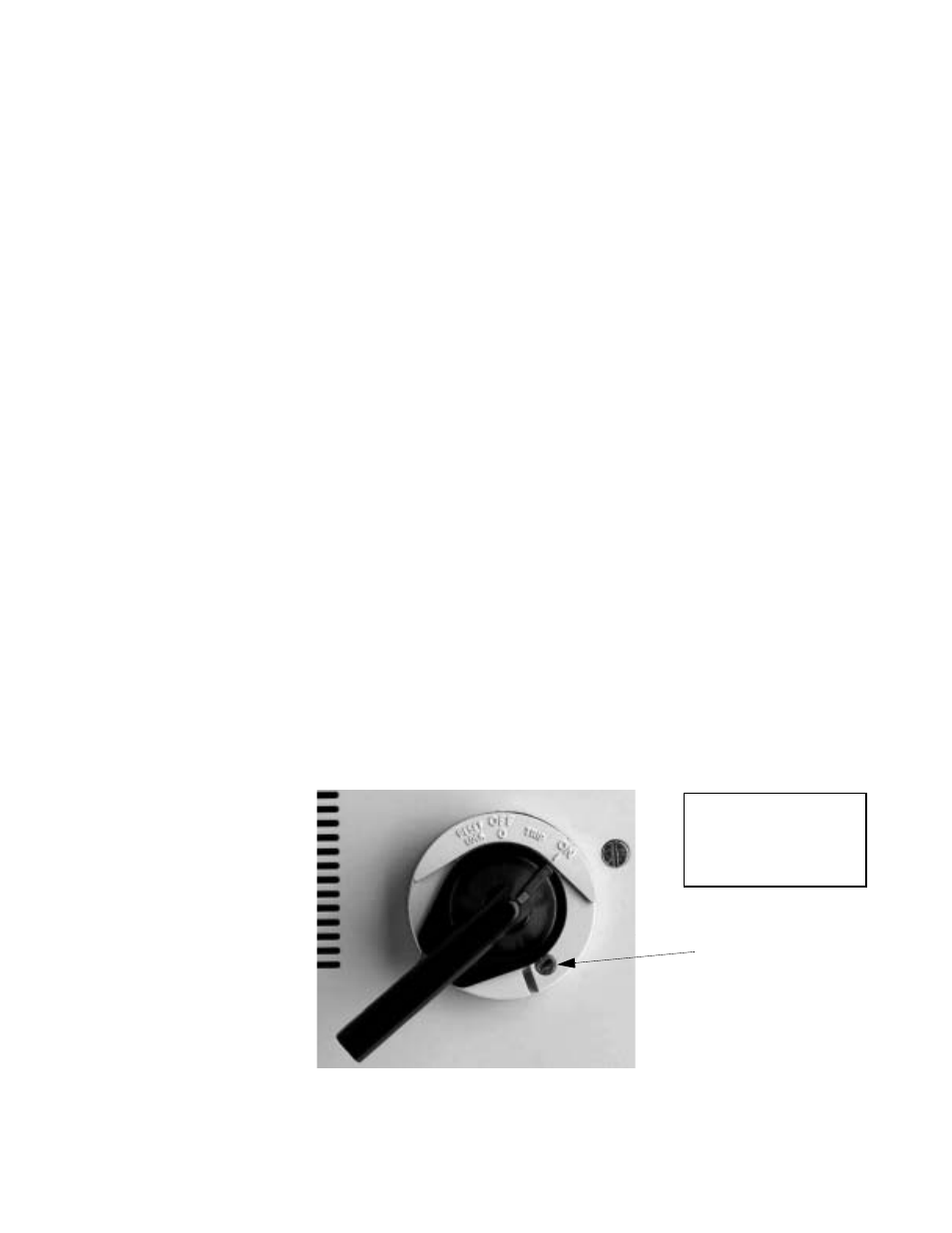
MCP Motor Circuit Protector Circuit Breaker/Disconnect
Electrically located on the input power side of the Bypass unit, the MCP adjustable, instantaneous trip circuit breaker
provides protection from short circuits for the motor power cables. The Bypass three phase input power connection is made to the
input terminals of the MCP. The door mounted rotary operating mechanism is a convenient means of disconnecting the Bypass
unit from line power for equipment maintenance. The MCP must be in the OFF position in order to open the enclosure door.
Service and troubleshooting personnel are provided with a means to defeat this door interlock. The rotary handle provides trip
indication and can be padlocked in the OFF position.
Fig 1.5 MCP Handle Positions – RESET/LOCK, OFF, TRIP, ON Shown in the “ON” position
Defeator
CAUTION
Only qualified service
personnel should use
the defeator feature.