Dip switch s1, Electrical installation 2 - 16 – Yaskawa P7B Drive Bypass User Manual
Page 54
Electrical Installation 2 - 16
!
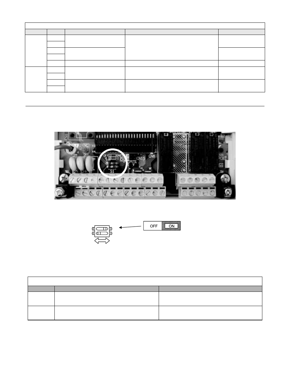
DIP Switch S1
DIP Switch S1 is described in this section. The functions of DIP switch S1 are shown in Table 2.7.
Fig 2.11 DIP Switch S1 Location
RS-485/
422
(Drive)
R+
Communication input
For 2-wire RS-485, short R+ to S+
and R- to S-.
Differential input,
optical isolation
R-
S+
Communication output
Differential input,
optical isolation
S-
IG
Signal common
-
-
Control
Power
Output
TB1-19
Damper Control
Pneumatic Control Interface
40VA@120V
TB1-20
TB1-21
Customer Use
Power Customer control Devices
100VA@120V
TB1-22
Table 2.7 DIP Switch S1
Name
Function
Setting
S1-1
RS-485 and RS-422 terminating resistance
OFF: No terminating resistance (Factory default)
ON: Terminating resistance of 110
Ω
S1-2
Input signal for analog input A2
OFF: 0-10 VDC (internal resistance: 20 K
Ω
)
ON: 4-20 mA (internal resistance: 250
Ω
) (Factory default)
Table 2.6 Bypass Control Circuit Terminals (Continued)
Type
No.
Signal Name
Function
Signal Level
S1
O
1
Terminating
resistance
DIP Switch S1-1 located on
terminal board.
2
1