Yaskawa P7B Drive Bypass User Manual
Page 210
Maintenance 7 - 4
!
Replacing Control Panel indicating lights or selector switches
Control panel pilot lights are modular, replaceable LEDs with a MTBF of 100,000 hours. LED type indicating lights are pro-
vided to improve the reliability well beyond that of incandescent bulbs.
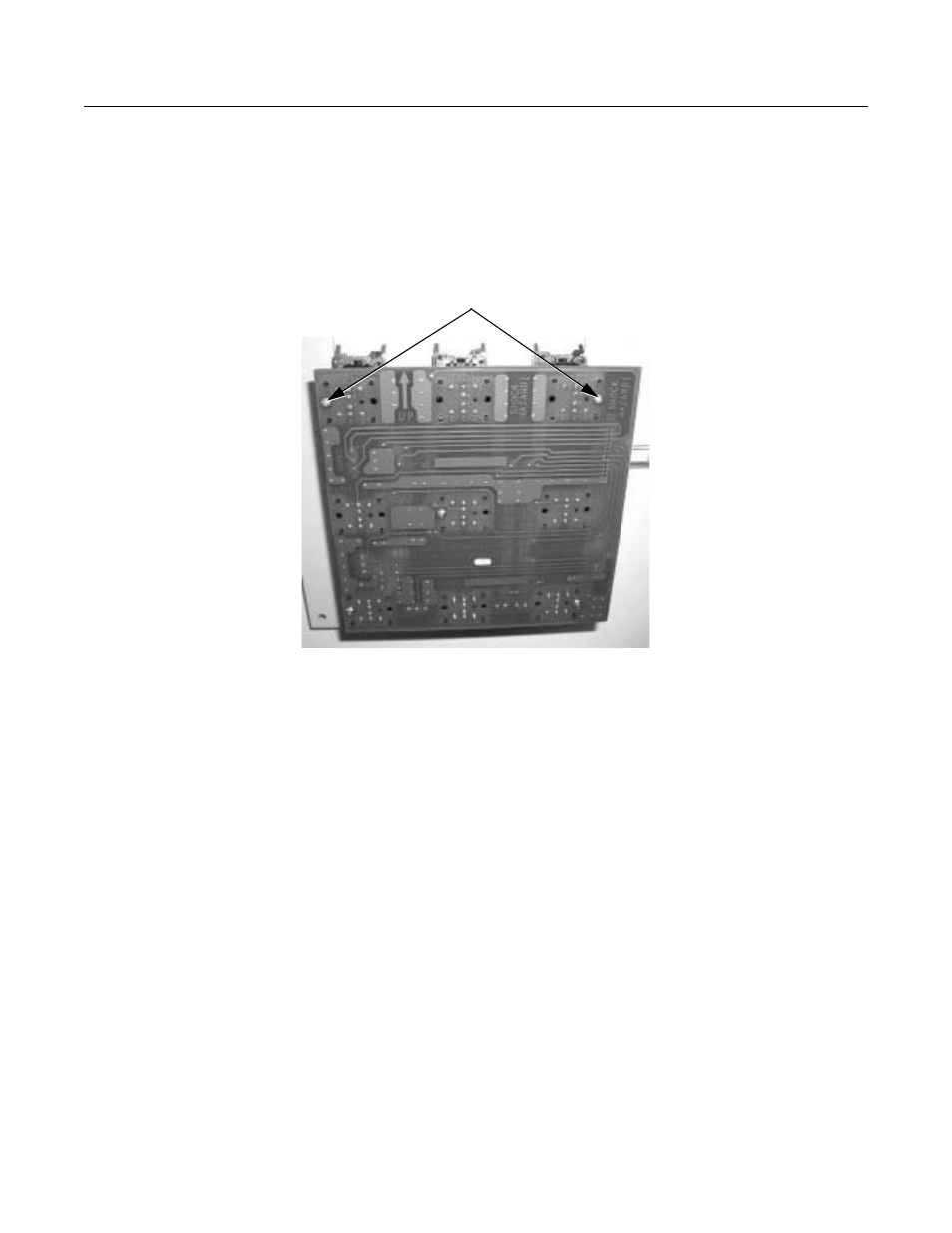
To remove and replace the LEDs, remove 9 screws from the “Bypass Operator Interface PCB A3” located on the inside of the
enclosure door mounted Operator Panel.
Fig 7.1 Removing PCB A3
PCB A3 will then lift off, exposing the LEDs and selector switch assemblies. Remove the ribbon cable connection from
CN203 as well as marking and disconnecting the terminations from CN204, CN205, CN206 and CN207, if required, to gain
access to the LED side of the circuit board A3.
To replace an individual LED, slide a small blade screwdriver beside the LED module and the retaining tabs on the socket that
is soldered to the circuit board, see Figure 7.2.
PCB Mounting
Screws, 9 places