Yaskawa P7B Drive Bypass User Manual
Page 217
Maintenance 7 - 11
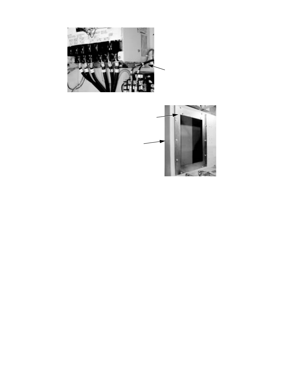
Fig 7.9 Drive Bottom Mounting Bracket
Fig 7.10 Back Panel and Reinforcing Frame
To free the Drive, remove the bolts from the Drive mounting brackets (remove the bottom first). When free, pull the Drive
through the front of the Bypass enclosure by guiding the heat sink back through the opening in the back panel.
With the Drive out of the Bypass assembly, remove the mounting brackets from the old Drive by removing the bolts affixing
the mounting brackets to the Drive. Attach the mounting brackets to the new Drive using the bolts from the old Drive.
#
Installing the Replacement Drive
Place the new Drive into the Bypass by sliding the heat sink through the opening in the rear of the Bypass enclosure. Line up
the holes on the mounting brackets with the holes in the reinforcing frame of the Bypass assembly. Use the mounting bolts
previously removed to re-affix the Drive to the Bypass back panel.
When the new Drive has been mounted in the Bypass enclosure, reconnect all power wiring and verify by checking the Bypass
schematic.
Re-mount the control terminal card to the Drive by sliding the terminal card into the connector (CN8) on the control circuit
board. Re-fasten the captive screws to the control PCB. Consult page 7-9 for detailed instructions.
Re-mount any option card, and re-connect all wiring from the option card to the Drive. Be sure to re-connect the ground wire
to the Drive.
With the Drive replacement complete, return power to the Bypass unit. Locate the start-up procedure for the Bypass in
Chapter 4 and follow the complete start-up procedure.
Drive Bottom Bracket
Bypass Enclosure
Back Panel
Reinforcing
Frame