Yaskawa P7B Drive Bypass User Manual
Page 216
Maintenance 7 - 10
Disconnect the cable from the Drive to the front panel mounted Digital Operator at the Drive end of the cable.
If a LonWorks option card is present, leave all the wires connected to the option card, disconnect the option card ground wire
at the Drive end and remove the option card from the Drive.
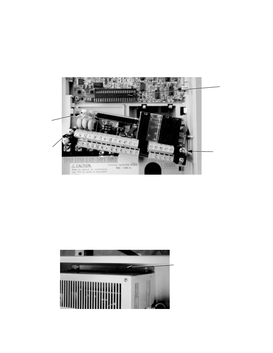
Leave the field control wiring connected to the removable control terminal card and remove the control terminal card from the
Drive. Two captive screws on either side of the terminal card must be loosened, the ground wire removed from terminal FE,
and the terminal card must be separated from the control circuit board by sliding the terminal card off its Connector (CN8). Do
this carefully by pulling down evenly on both sides of the terminal card. See also page 7-9 for detailed instructions.
Fig 7.7 Removable Control Terminal Card
The power terminal block for the three phase input and output power connections is not removable. All connections to the
power terminal block must be removed. Do not overlook the Drive ground wire. It is behind other wiring and will probably be
removed last. Observe the wire and terminal markings for all power wires, to ensure correct re-wiring to the new Drive. The
wires are labeled from the factory, but re-label any wires where labels may no longer be legible. Refer to Chapter 2 Electrical
Installation and the schematic diagram that was shipped with the original Bypass unit.
Once all wiring has been disconnected from the Drive, the Drive is ready to be removed from the enclosure.
Drives located in Bypass units are mounted differently than stand alone drives. A Drive in a Bypass unit is mounted such that
the heat sink is external to the enclosure. Mounting brackets are located on the top and bottom of the Drive, between the Drive
and the Drive’s heat sink. These brackets are bolted to the reinforced Bypass back panel with the heat sink projecting through
an opening in the back panel and reinforcing frame.
Fig 7.8 Drive Top Mounting Bracket
Connector
Terminal
FE
CN8
Captive
Mounting
Screw
Captive
Mounting
Screw
Drive Top Bracket