Yaskawa P7B Drive Bypass User Manual
Page 26
Physical Installation 1 - 14
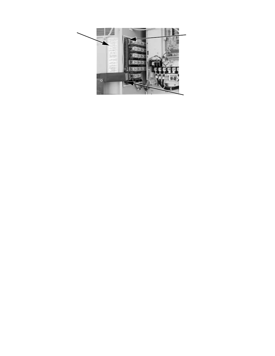
Fig 1.8 Control Terminal Strip
"
Contactors
The Bypass is a “3 contactor Bypass” circuit employing IEC rated contactors in an electrically interlocked arrangement to
allow mutually exclusive operation in Drive or Bypass modes. To minimize enclosure space requirements, they are mounted in
a 3 contactor assembly.
The control logic and “soft start” characteristic of the Drive limit the Drive input and output contactors to motor FLA current
or less. For this reason, the Drive input and output contactors have lower current ratings than the Bypass contactor. The Bypass
contactor is exposed to motor inrush current (LRA) when starting the motor across-the-line and therefore requires a higher
current rating.
"
OverLoad Relay
The OverLoad Relay (OLR) is mounted to the contactor assembly or back panel (depending on rating), just above the Bypass
contactor (see Figure 1.7). Electrically on the output power side of the Bypass unit, the adjustable thermal OLR provides
overload protection for the motor in both the Drive and Bypass operating modes. The Bypass three phase output power
connection to the motor is made to the output terminals of the overload relay. The OLR is set up in the factory to be a manual
reset device, requiring operator attention if an overload trip-out is experienced.
"
Control Power Transformer
A Control Power Transformer (CPT) is provided to power the Bypass 120 VAC control circuit. The VA capacity is determined
by the control circuit and optional functions specified for the unit. 100 VA of extra transformer capacity for customer control
logic is provided in the standard unit and additional capacity is available as an “engineered” or “custom” option. The CPT
primary is fused in both legs, the secondary is fused when required by NEC (above 350 VA). One side of the transformer
secondary is grounded to the Bypass enclosure.
"
Relay and Selector Switch Logic
Operating elements such as indicating lights and selector switches, as well as the control relay logic, have been incorporated
into a PCB assembly to eliminate the potential for loose wires after shipment and to control factory costs.
The operating elements are located on PCB A3, mounted to the inside of the enclosure door and ribbon cable connected to the
control relay logic PCB A2.
The control relay logic PCB A2 is mounted to the left hand side of the enclosure and contains the control circuit field wiring
terminal strip (TB1).
"
Drive/Bypass logic interlocks explained
The Bypass 120 VAC relay logic circuit is interconnected with the Drive multi-function digital input terminals and multi-
function digital output terminals to allow a single customer interface to control both Drive and Bypass circuits. Some of these
terminals are therefore not available for other field use.
TB1 Label Defining
TB1 with Terminal Numbers
Printed on the PCB
Slide Switches for switch
Customer Control
selectable functions (Auto
Transfer, Remote Transfer and
Smoke Purge) are behind this
ribbon cable connector. See
Fig. 1.9 for details.
Circuit Connection
Points