Yaskawa P7B Drive Bypass User Manual
Page 106
Programming 5 - 12
If you want the Drive to follow the speed command set by the digital operator: Use the HAND mode by turning the
HAND/OFF/AUTO selector switch to HAND. The speed command can then be entered into the U1-01 monitor parameter in
the
“-DRIVE-” Menu.
If you want the Drive to follow an AUTO analog speed command: Connect a 0 – 10 VDC speed command signal between
terminals A1 and AC or a 4 – 20 mA speed command signal to terminals A2 and AC. Select the AUTO position of the Hand/
Off/Auto switch.
If you want the Drive to receive the speed command from serial communication: Set the parameter indicated in Table 5.2
for the desired serial communication option. Connect the RS-485/422 serial communications cable to terminals R+, R-, S+,
and S- on the control I/O terminal block. The HAND/OFF/AUTO selector switch must be in the AUTO position.
"
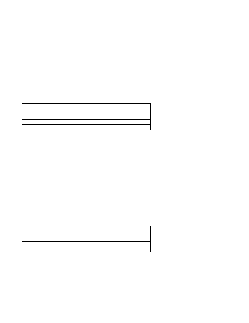
b1-02 Run Source
To successfully operate the Drive or Bypass and motor remotely, an external run command must be received by the Drive and
Bypass unit. Parameter b1-02 specifies from where the run command for the Drive will be accepted.
This parameter is by default set to “1: Terminals.” This setting is required by the Bypass logic circuit.
To issue a run command from the control panel: Turn the Hand/Off/Auto switch to the HAND position.
To issue a run command from a remote source: Turn the Hand/Off/Auto switch to the AUTO position. A contact closure
between terminals TB1-3 and TB1-4 will control the Drive or Bypass start and stop operation.
To issue a run command via serial communication: Set the parameters indicated in Table 5.2 for the desired serial commu-
nication option. Connect the RS-485/422 serial communication cable to R+, R-, S+, and S- on the removable terminal block.
"
b1-03 Stopping Method
There are four methods of stopping the Drive when the Run command is removed.
“0:Ramp to stop”: When the Run command is removed, the Drive will decelerate the motor to 0 rpm. The rate of deceleration
is determined by the active deceleration time. The factory default Decel Time is in parameter C1-02.
Setting
Description
0
Operator
1
Terminals (factory default)
2
Serial Com
3
Option PCB
Setting
Description
0
Ramp to Stop (factory default)
1
Coast to Stop
2
DC Injection to Stop
3
Coast w/Timer