Removing and replacing drive in a bypass unit, Removing and replacing the drive in a bypass unit – Yaskawa P7B Drive Bypass User Manual
Page 215
Maintenance 7 - 9
Removing and Replacing the Drive in a Bypass Unit
!
Drive Replacement
If possible, save the existing drive programming by copying it to the memory in the keypad/operator via parameter o3-01.
When it has been determined that a Drive fault requires a Drive replacement (see Chapter 6), there are several steps required
before the Bypass will be operable again. First, a new Drive must be ordered. Begin by determining the model number Drive
that is in the Bypass assembly.
Drive Model Number:_____________________________
Warranty status determines whom you should contact to obtain a new Drive.
For a Bypass unit that is still under warranty, begin by contacting Yaskawa Technical Support: 1-800-YASKAWA (927-5292),
dial 2 for Inverter and Drive Products, then 5 for technical support. Technical support may also be reached through e-mail at
[email protected].
A Yaskawa distributor should be contacted to replace a Drive that is no longer under warranty.
When the Drive arrives, verify that the Drive is the correct model number.
#
Removing the Drive
Before installing the new Drive, the old Drive must be removed from the Bypass assembly. As a safety precaution, disconnect
the AC power line coming into the main Bypass circuit breaker to ensure that no power is in the Bypass unit.
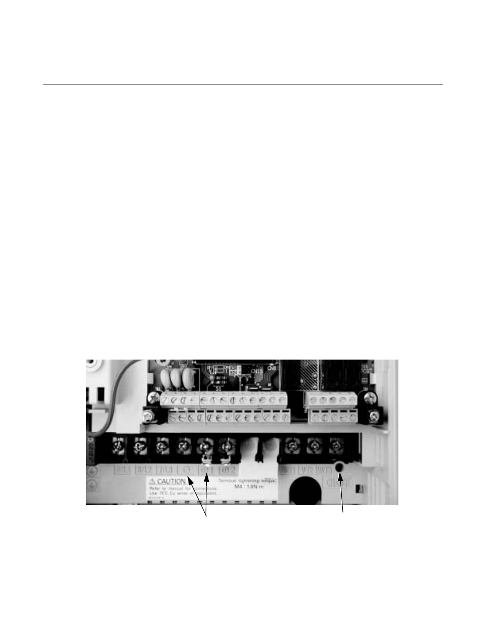
Check the Drive DC Bus voltage to be sure it is at a safe level before working inside the Bypass enclosure. DC Bus voltage can
be monitored by the CHARGE status indicator LED, near the power terminals. Be sure the LED is extinguished before pro-
ceeding. Another method is to measure the DC voltage across terminals “+1” and “-” on the power terminal block.
Fig 7.6 Drive Power Terminal Block
Terminal for DC
Bus Voltage
DC Bus CHARGE Status
Indicator LED