Yaskawa MP900 Series Machine Controller New Ladder Editor User Manual
Page 138
1 Ladder Program Instructions
1.7.4 PI CONTROL Instruction (PI)
1-128
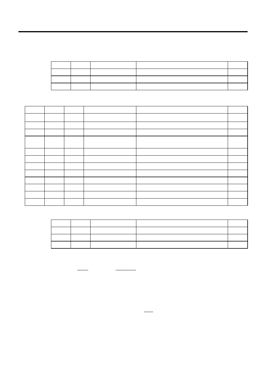
* Relay I/O Bit Assignment
* Relay I/O Bit Assignment
Here, the PI operation is expressed as follows:
The following operation is performed within the PI instruction:
BIT
Symbol
Name
Specifications
I/O
0
IRST
Integration reset
"ON" is input when integration is reset
IN
1 to 7
−
(Reserved)
Reserved relay for input
IN
8 to F
−
(Reserved)
Reserved relay for output
OUT
Table 1.13 Real Number Type PI Instruction Parameters
ADR
Type
Symbol
Name
Specifications
I/O
0
W
RLY
Relay I/O
Relay input, relay output
∗
IN/OUT
1
W
−
(Reserved)
Reserved register
−
2
F
Kp
P gain
Gain of the P offset
IN
4
F
Ki
Integration adjustment
gain
Gain of the integration circuit input
IN
6
F
Ti
Integration time
Integration time (s)
IN
8
F
IUL
Upper integration limit
Upper limit for the I offset
IN
10
F
ILL
Lower integration limit
Lower limit for the I offset
IN
12
F
UL
Upper PI limit
Upper limit for the P + I offset
IN
14
F
LL
Lower PI limit
Lower limit for the P + I offset
IN
16
F
DB
PI output dead band
Width of the dead band for the P + I offset
IN
18
F
Y
PI output
PI offset output (also output to the A register)
OUT
20
F
Yi
I offset
I stored
OUT
BIT
Symbol
Name
Specifications
I/O
0
IRST
Integration reset
"ON" is input when integration is reset
IN
1 to 7
−
(Reserved)
Reserved relay for input
IN
8 to F
−
(Reserved)
Reserved relay for output
OUT
Y
1
X
= Kp + Ki ×
Ti
× S
X: deviation input value
Y: output value
Ti
Y
= Kp × X + {(Ki ×X + IREM) /
Ts
+ Yi }
Yi : previous output value
Ts: scan time setting
,
,