7 first-order lag instruction (lag), Outline – Yaskawa MP900 Series Machine Controller New Ladder Editor User Manual
Page 149
1.7 DDC Instructions
1-139
1
1.7.7 FIRST-ORDER LAG Instruction (LAG)
Outline
The LAG instruction calculates the first-order lag according to the contents of a previously
set parameter table. The input (Input) to the LAG operation must be integer or real number
data.
Double-length integer data cannot be used. The configurations of the parameter tables for
integer and real number data are different. Operations are performed by processing each
parameter as an integer consisting of the lower-place 16 bits.
* Relay I/O Bit Assignment.
* Relay I/O Bit Assignment
Here, the LAG operation is expressed as follows:
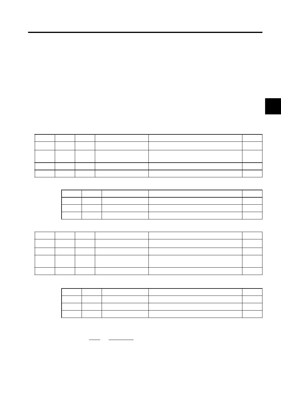
Table 1.18 Integer Type LAG Instruction Parameters
ADR
Type
Symbol
Name
Specifications
I/O
0
W
RLY
Relay I/O
Relay input, relay output
∗
IN/OUT
1
W
T
First-order lag time con-
stant
First-order lag time constant (ms)
IN
2
W
Y
LAG output
LAG output (also output to the A register)
OUT
3
W
REM
Remainder
Remainder stored
OUT
BIT
Symbol
Name
Specifications
I/O
0
IRST
LAG reset
"ON" is input when LAG is reset.
IN
1 to 7
−
(Reserved)
Reserved relay for input
IN
8 to F
−
(Reserved)
Reserved relay for output
OUT
Table 1.19 Real Type LAG Instruction Parameters
ADR
Type
Symbol
Name
Specifications
I/O
0
W
RLY
Relay I/O
Relay input, relay output
∗
IN/OUT
1
W
−
(Reserved)
Reserved register
−
2
F
T
First-order lag time con-
stant
First-order lag time constant (s)
IN
4
F
Y
LAG output
LAG output (also output to the F register)
OUT
BIT
Symbol
Name
Specifications
I/O
0
IRST
LAG reset
"ON" is input when LAG is reset.
IN
1 to 7
−
(Reserved)
Reserved relay for input
IN
8 to F
−
(Reserved)
Reserved relay for output
OUT
Y 1
X
=
1 + T
S
; ie. T
(dY/dt) + Y
= X
×
×