13 pulse width modulation instruction (pwm), Outline – Yaskawa MP900 Series Machine Controller New Ladder Editor User Manual
Page 173
1.7 DDC Instructions
1-163
1
1.7.13 PULSE WIDTH MODULATION Instruction (PWM)
Outline
The PWM instruction converts the value of the Input to PWM as an input value (between -
100.00 and 100.00%, with increments of 0.01%) and outputs the result to the Output and the
parameter table.
Double-length integer and real number operations are not allowed.
X: input value
Ts: scan time set value (ms)
When 100.00% is input: all ON
When 0% is input: 50% duty (50% ON)
When -100.00% is input: all OFF
When the PWM reset (PWMRST) is ON, all internal operations are reset and PWM opera-
tions are performed with that instant as the starting point. After turning the power ON, set
PWMRST to ON to clear all internal operations, then use the PWM instruction.
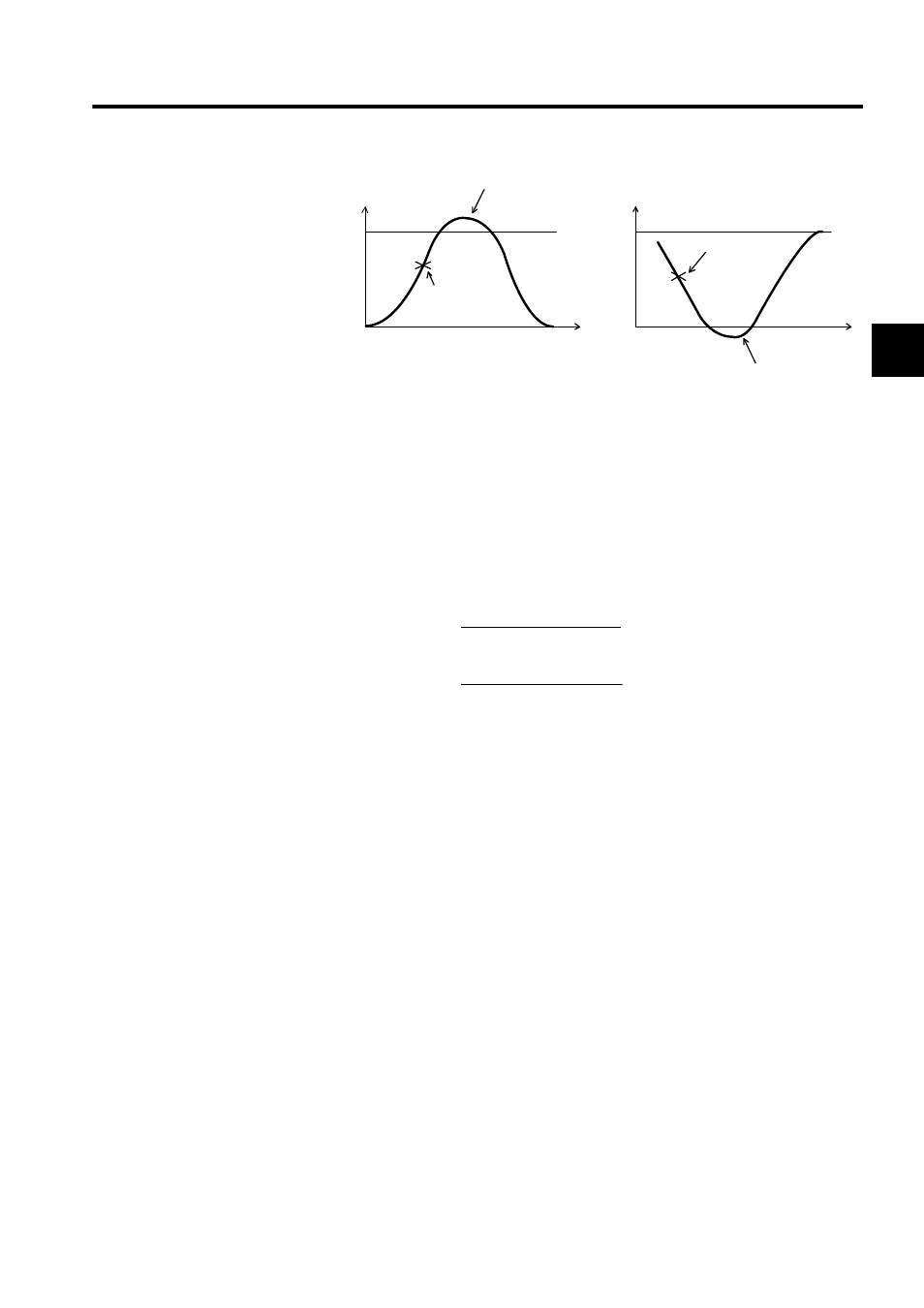
Speed
VI
0
Overshooting
(*S) the instruction
(input value)
changes while accelerating.
(Change to VI
0)
Time
Instruction (input value)
change in moderation
VI)
Speed
V I
0
Undershoot
Time
→
→
(Change to 0
PWMT (X + 10000 )
Time of ON output =
20000
PWMT ( X + 10000 )
Number of ON outputs =
Ts
× 20000