Super Systems 20Q User Manual
Page 107
103
AUXILIARY INPUT
AUXILIARY INPUT
AUXILIARY INPUT
AUXILIARY INPUT
AUXILIARY INPUT
Type:
Type:
Type:
Type:
Type: NOT isolated linear input.
Function
Function
Function
Function
Function: Programmable as remote set point input or bias on
the local set point.
Read-out
Read-out
Read-out
Read-out
Read-out: keyboard programmable between -1999 and +9999.
Temperature drift
Temperature drift
Temperature drift
Temperature drift
Temperature drift: < 300 ppm.
Sampling time:
Sampling time:
Sampling time:
Sampling time:
Sampling time: 500 ms.
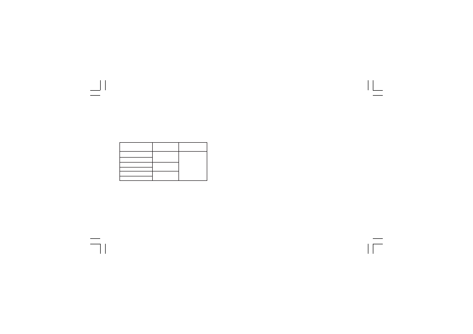
STANDARD RANGES TABLE
LOGIC INPUTS
LOGIC INPUTS
LOGIC INPUTS
LOGIC INPUTS
LOGIC INPUTS
The instrument may be supplied with 3 logic inputs each one of
them can be programmed as:
- Set point selection (SP-SP2)
- Set point selection (SP3-SP4)
- Local/remote set point selection
- Auto/manual selection
- Output limiter activation
- Data Hold of the measured value
- Manual reset of the alarms
(acknowledge)
- Reverse/direct control action
Input type: Contact closure (voltage free).
Active logic level:
Active logic level:
Active logic level:
Active logic level:
Active logic level: Close or open programmable.
ADDITIONAL LOGIC INPUTS
ADDITIONAL LOGIC INPUTS
ADDITIONAL LOGIC INPUTS
ADDITIONAL LOGIC INPUTS
ADDITIONAL LOGIC INPUTS
The instrument may be supplied with 4+4 additional logic inputs.
Function
Function
Function
Function
Function: Input status visible on the display or by serial link.
Input type
Input type
Input type
Input type
Input type: Contact closure (voltage free).
Active logic level:
Active logic level:
Active logic level:
Active logic level:
Active logic level: Close or open programmable.
Contact rating
Contact rating
Contact rating
Contact rating
Contact rating: 5 V DC, 2.5 mA
CURRENT TRANSFORMER INPUT FOR OUT FAILURE
CURRENT TRANSFORMER INPUT FOR OUT FAILURE
CURRENT TRANSFORMER INPUT FOR OUT FAILURE
CURRENT TRANSFORMER INPUT FOR OUT FAILURE
CURRENT TRANSFORMER INPUT FOR OUT FAILURE
DETECTION
DETECTION
DETECTION
DETECTION
DETECTION
The instruments equipped with this feature are capable, by
means of a CT, to detect and signal a possible failure of the line
driven by a control output programmed as a time proportioning
output (see "OUT failure detection").
Input range
Input range
Input range
Input range
Input range: 50 mA AC.
Scaling
Scaling
Scaling
Scaling
Scaling: programmable from 10 A to 100 A (with 1 A step).
Input type
Input type
Input type
Input type
Input type
0 - 20 mA
0 - 20 mA
0 - 20 mA
0 - 20 mA
0 - 20 mA
4 - 20 mA
4 - 20 mA
4 - 20 mA
4 - 20 mA
4 - 20 mA
0 - 5 V
0 - 5 V
0 - 5 V
0 - 5 V
0 - 5 V
1 - 5 V
1 - 5 V
1 - 5 V
1 - 5 V
1 - 5 V
0 - 10 V
0 - 10 V
0 - 10 V
0 - 10 V
0 - 10 V
2 - 10 V
2 - 10 V
2 - 10 V
2 - 10 V
2 - 10 V
impedance
impedance
impedance
impedance
impedance
< 5
Ω
> 200 k
Ω
> 400 k
Ω
A c c u r a c y
A c c u r a c y
A c c u r a c y
A c c u r a c y
A c c u r a c y
0.2 % + 1 digit
@ 25°C
mkc-ssi.pmd
06/07/2004, 12.20
103