Super Systems 20Q User Manual
Page 13
9
NOTES
NOTES
NOTES
NOTES
NOTES:
1) This input is not isolated
not isolated
not isolated
not isolated
not isolated from measuring input. A double or
reinforced insulation between instrument output and power
supply must be assured by the external element.
2) Do not run current transformer input wiring together with AC
power cables.
3) The minimum active period to perform this measurement is
equal to 120 ms.
4) The input impedance is equal to 20
Ω
.
14
15
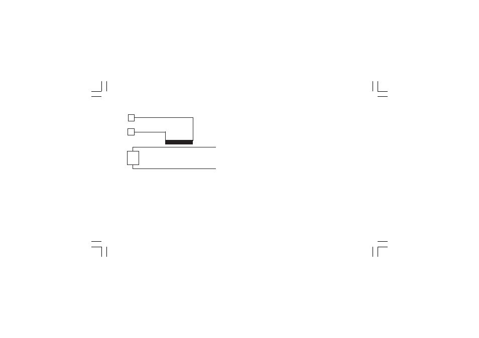
Load
Current
transformer
D) CURRENT TRANSFORMER INPUT
D) CURRENT TRANSFORMER INPUT
D) CURRENT TRANSFORMER INPUT
D) CURRENT TRANSFORMER INPUT
D) CURRENT TRANSFORMER INPUT
Fig. 10 CURRENT TRANSFORMER INPUT
WIRING
This input allows you to measure and display the current running
in the load, driven by a time proportional control output, during
the ON and OFF periods of the output cycle time. By this feature
it is also available the "Output failure detection" function (see
page 66).
mkc-ssi.pmd
06/07/2004, 12.19
9