Super Systems 20Q User Manual
Page 46
CnF. 2CnF. 2CnF. 2CnF. 2CnF. 2
42
CONFIGURATION GROUP 3 [C.Fxx]
CONFIGURATION GROUP 3 [C.Fxx]
CONFIGURATION GROUP 3 [C.Fxx]
CONFIGURATION GROUP 3 [C.Fxx]
CONFIGURATION GROUP 3 [C.Fxx]
CONTROL OUTPUT CONFIGURATION
- Split range - [C.F01]
- Split range - [C.F01]
- Split range - [C.F01]
- Split range - [C.F01]
- Split range - [C.F01]
This parameter will be available only when two control outputs
are configured.
Range: dIS
= Split range feature is not required
Enb
= Split range feature is required
NOTE about the split range
NOTE about the split range
NOTE about the split range
NOTE about the split range
NOTE about the split range.
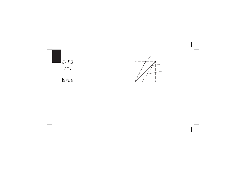
This function allows you to drive by the same control action, two
physical outputs (two actuators) with different bias and gain.
The relation between the Calculated Power Output and the
resulting real outputs are shown below:
where:
- for the first split output (MAIN)
Bias 1 = -A
Gain 1 = 100 / (B - A)
- For the second split output (SECONDARY)
Bias 2 = -C
Gain 2 = 100 / (D - C)
FOR EXAMPLE
FOR EXAMPLE
FOR EXAMPLE
FOR EXAMPLE
FOR EXAMPLE:
Let's suppose that the first split output operates from 0 % to
33.3 % of the calculated output while the second one operates
from 33.3 % to the 100 % of the calculated output.
A
B
C
D
0 %
100 %
100 %
Calculated
PWR Output
Real PWR
Output
First split
output (MAIN)
Standard curve
Second split
output
(Secondary)
CnF.3CnF.3CnF.3CnF.3CnF.3
mkc-ssi.pmd
06/07/2004, 12.19
42