Super Systems 20Q User Manual
Page 55
CnF. 4CnF. 4CnF. 4CnF. 4CnF. 4
51
CONFIGURATION GROUP 5 [C.Hxx]
CONFIGURATION GROUP 5 [C.Hxx]
CONFIGURATION GROUP 5 [C.Hxx]
CONFIGURATION GROUP 5 [C.Hxx]
CONFIGURATION GROUP 5 [C.Hxx]
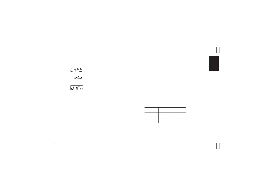
DIGITAL INPUT/OUTPUT CONFIGURATION
- Logic input 1 function - [C.H01]
- Logic input 1 function - [C.H01]
- Logic input 1 function - [C.H01]
- Logic input 1 function - [C.H01]
- Logic input 1 function - [C.H01]
Range: nonE = Input contact not used
SP1.2 = Input contact used for SP /SP2 set point
selection (see note 2)
SP3.4 = Input contact used for SP3/SP4 set point
selection (see note 2)
SP.L.r = Input contact used for Local/Remote set point
selection (Remote when logic level is “1”)
Au.ñA = Input contact used for Auto/Manual selection
(Manual when logic level is “1”)
O.LIñ = Input contact used for output limiter activation
(Output limited when logic level is “1”)
Hold = Input contact used to stop input sampling (Hold
function) (Stop sampling when logic level is “1”)
ñ.rSt = Input contact used to reset (acknowledge) alarm
(Reset when logic level is “1”)
rE.dr = Input contact used for Reverse/Direct control
action selection (Direct when logic level is “1”)
NOTES
NOTES
NOTES
NOTES
NOTES:
1) When logic input circuits are not mounted the middle display
will show “no.Pr” (not present).
2) When one logic input is set to “SP.1.2” and no other logic
input is set to “SP.3.4”, the relation between the logic level
and the selected set point is the following:
Logic level 0 = SP
Logic level 1 = SP2
When one logic input is set to “SP.1.2” and a second logic
input is set to “SP.3.4”, the relation between the logic levels
and the selected set point is the following:
“SP.3.4”
“SP.1.2”
Set point
level
level
selected
0
0
SP
0
1
SP2
1
0
SP3
1
1
SP4
CnF.5CnF.5CnF.5CnF.5CnF.5
mkc-ssi.pmd
06/07/2004, 12.19
51