Super Systems 20Q User Manual
Page 7
Advertising
3
Connections are to be made with the instrument housing
installed in its proper location.
A) MEASURING INPUTS
A) MEASURING INPUTS
A) MEASURING INPUTS
A) MEASURING INPUTS
A) MEASURING INPUTS
NOTE
NOTE
NOTE
NOTE
NOTE: Any external component (like zener barriers etc.)
connected between sensor and input terminals may
cause errors in measurement due to excessive and/or not
balanced line resistance or possible leakage currents.
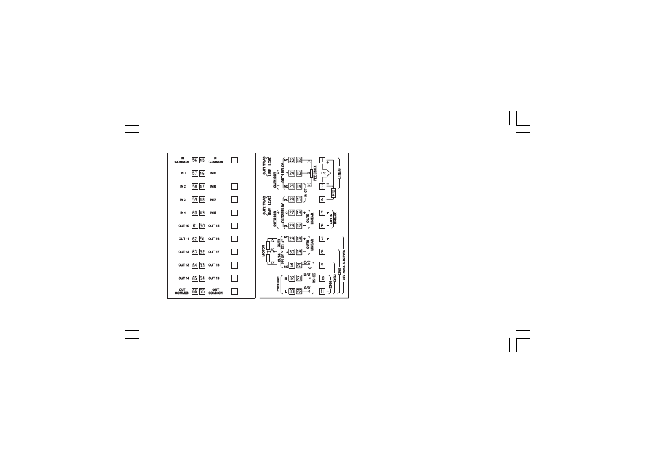
CONNECTION DIAGRAMS
CONNECTION DIAGRAMS
CONNECTION DIAGRAMS
CONNECTION DIAGRAMS
CONNECTION DIAGRAMS
Fig. 3
REAR TERMINAL BLOCK
mkc-ssi.pmd
06/07/2004, 12.19
3
Advertising