Super Systems 20Q User Manual
Page 24
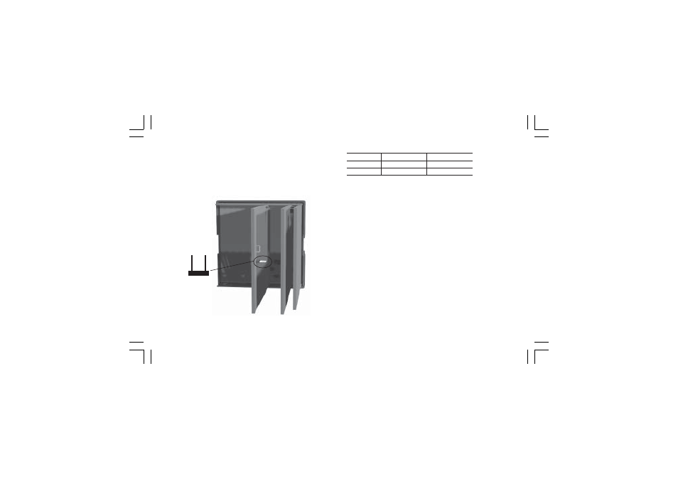
20
Output
J 204
J 205
Relay
close
open
Servo
open
close
NOTE
NOTE
NOTE
NOTE
NOTE: when the servomotor close loop or the servomotor open
loop with valve position indication outputs is required, it will be
necessary to set also V301 (see "IN CT/Feedback selection"
paragraph)
IN CT / FEEDBACK SELECTION
IN CT / FEEDBACK SELECTION
IN CT / FEEDBACK SELECTION
IN CT / FEEDBACK SELECTION
IN CT / FEEDBACK SELECTION
This instrument can use the "IN CT" input or the "Feedback"
input; the two inputs are not contemporarily.
The current transformer input allows you to measure and display
the current running in a load driven by a time proportional
control output during the ON and OFF periods of the output
cycle time. By this feature it is also available the "Out failure
detection" function (see page 111).
The feedback input is used when the servomotor close loop or
the servomotor open loop with valve position indication outputs is
required.
OUTPUT 3 AND 4 SELECTION
OUTPUT 3 AND 4 SELECTION
OUTPUT 3 AND 4 SELECTION
OUTPUT 3 AND 4 SELECTION
OUTPUT 3 AND 4 SELECTION
Output 3 and 4 can be set as:
- 2 independent relay outputs
- 1 servomotor output with interlocked contact.
Set J204 (see fig. 21) and J205 (see fig. 20) according to the
desired output type as shown in the following table.
J204
Fig.21
mkc-ssi.pmd
06/07/2004, 12.19
20